https://youtu.be/X_OInW3hLRk
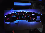
Breadboard testing appears to be working.
I probably couldn't have gotten it working without the oscilloscope. At least not on the bench and without danger to the car.
The fan controller was not an appropriate substitute at all. It doesn't appear to be an actual square wave at all and it was running about 25 khz. I suspect being it is a motor driver there may be some inductors involved? Haven't opened it. It is another part of the build to control 2 - 6" ventilation fans mounted in the rear 6"x9" location. I had it laying around and am impatient.
I played with trying to amplify the signal generator on the scope with some success, but I think I kept killing transistors so I just ordered the PWM generator.
The PWM signal passes directly through the controller to the 12v wire of the LEDs. The PWM is also tapped off to a low pass filter which is fed to a comparator. When the PWM is present it triggers a MOSFET to drive the coil on the relay which powers up the controller.
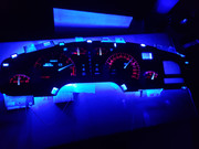
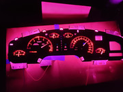
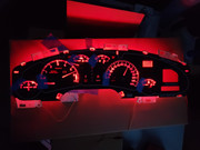
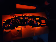
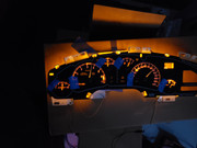
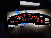
The controller handles the color mix and the vehicles PWM handles the brightness.
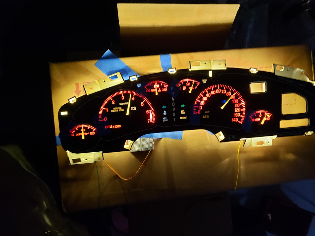
Being incandescent from factory I don't think the car will have any problem powering this instead.
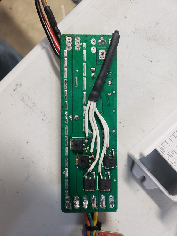
I'm not so sure I had to reroute the ground paths of the mosfets in the controller as I have both grounds tied together anyway? I did that before I had the P-channel / N-channel thing somewhat solidly grasped. Pretty sure the factory computer must use P-channel or something like that. That is how they get a single signal wire and can ground a load directly to the body. If an N-channel was used the ground has to come back to the computer or whatever controller to be switched and the load gets constant voltage. that is why all these controllers have PWM + and -. N-channel are cheaper.
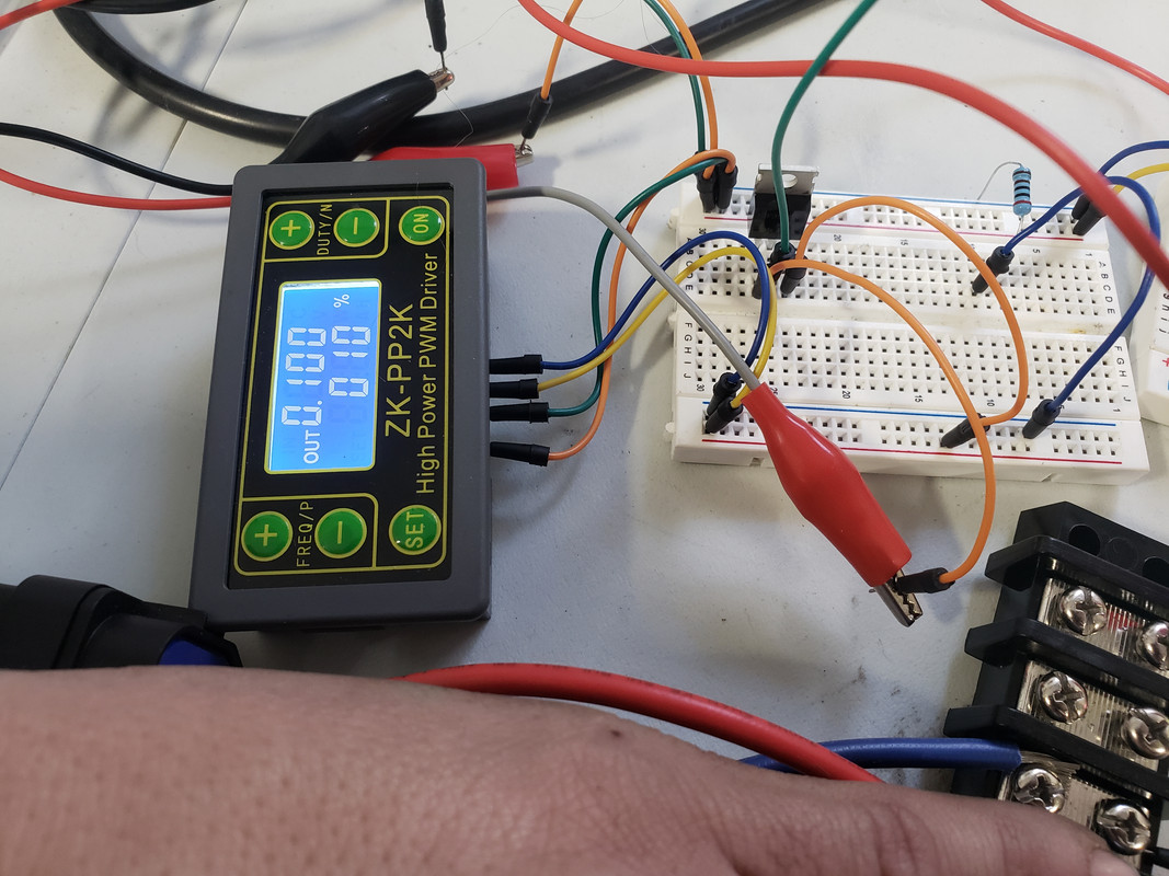
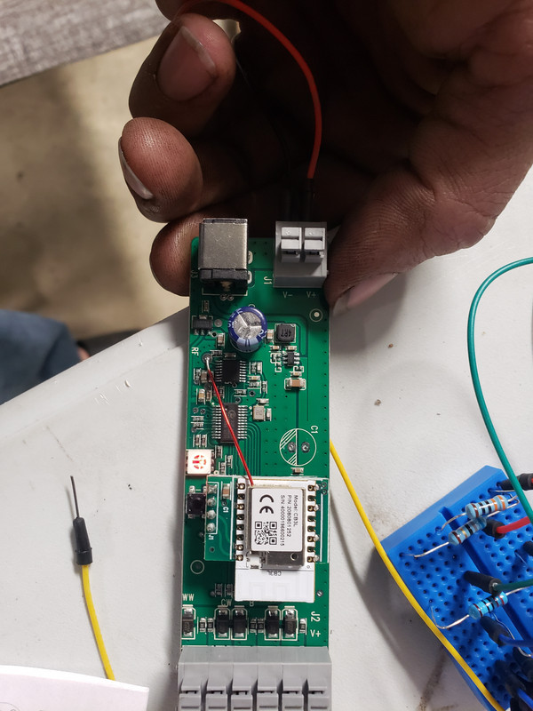
This is just the chunk to simulate the PWM for bench testing.
I had to add a P-channel mosfet with the blue breadboard to the PWM generator to simulate the PWM as the vehicle uses. Due to this just turning the controller off makes the output go to 12v, so as a workaround just to bench test I just plug and unplug the wire. An additional side effect of this is the settings on the controller. Adding that MOSFET flips the duty cycle. The factory range seems to be 40% to 90% Duty @ 100hz. My equivalent settings are 60% to 10% Duty @ 100hz. 10% being the brightest. Basically controlling the duty cycle for the off time instead of the on time.
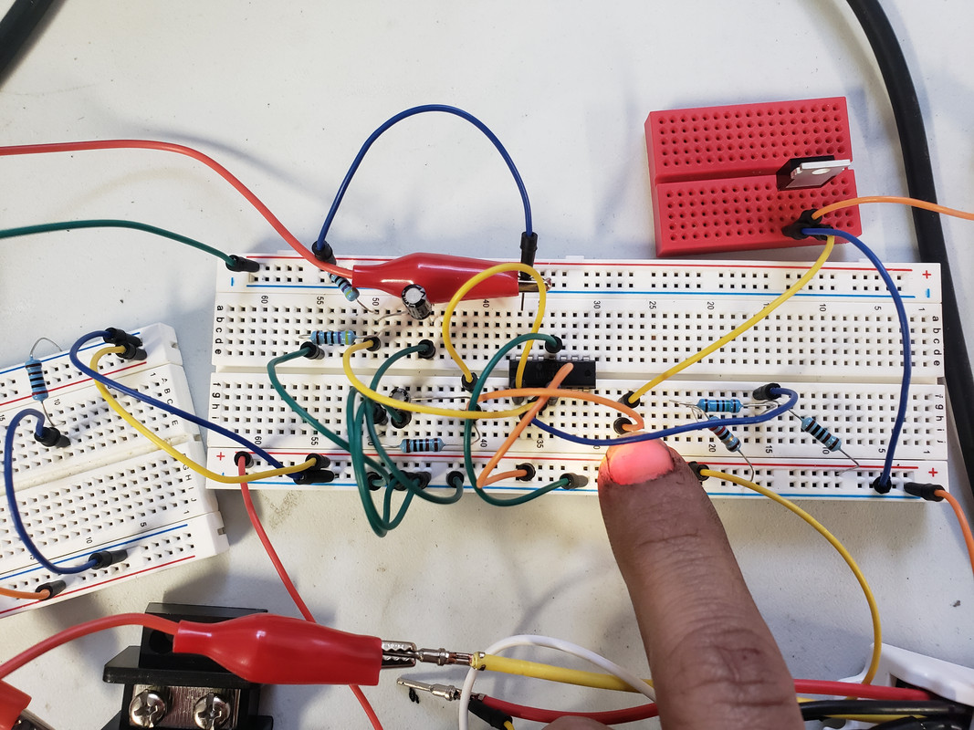
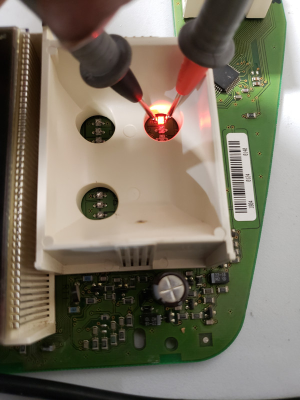
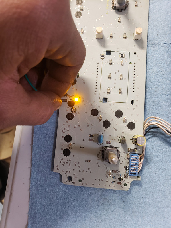
This is the lowpass filter / comparator part. The red breadboard is the driver MOSFET for the relay coil. (Relay is massive overkill, but I like to keep systems separate and I like those style relays.)
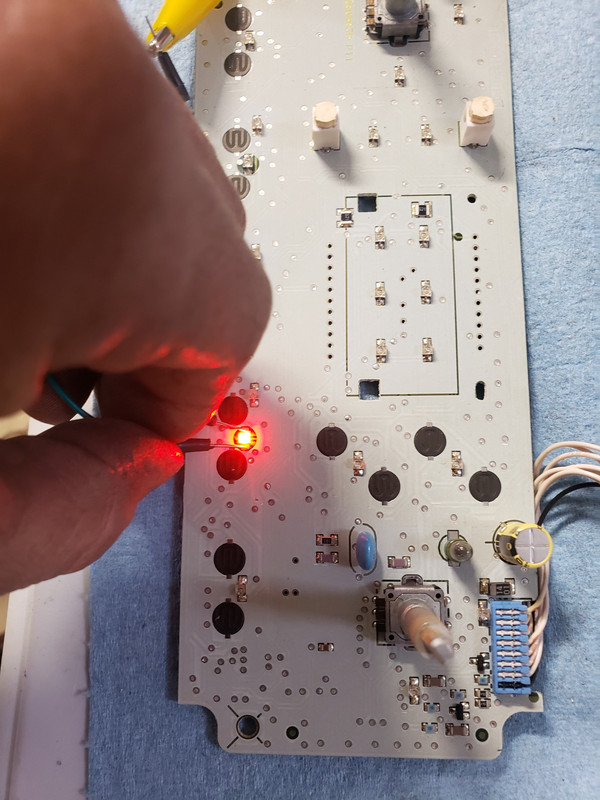
The LED I'm covering up was just an indicator if I had signal going to the relay coil driver.
Next on this part will be to generate a BOM of automotive rated components and layout a board.
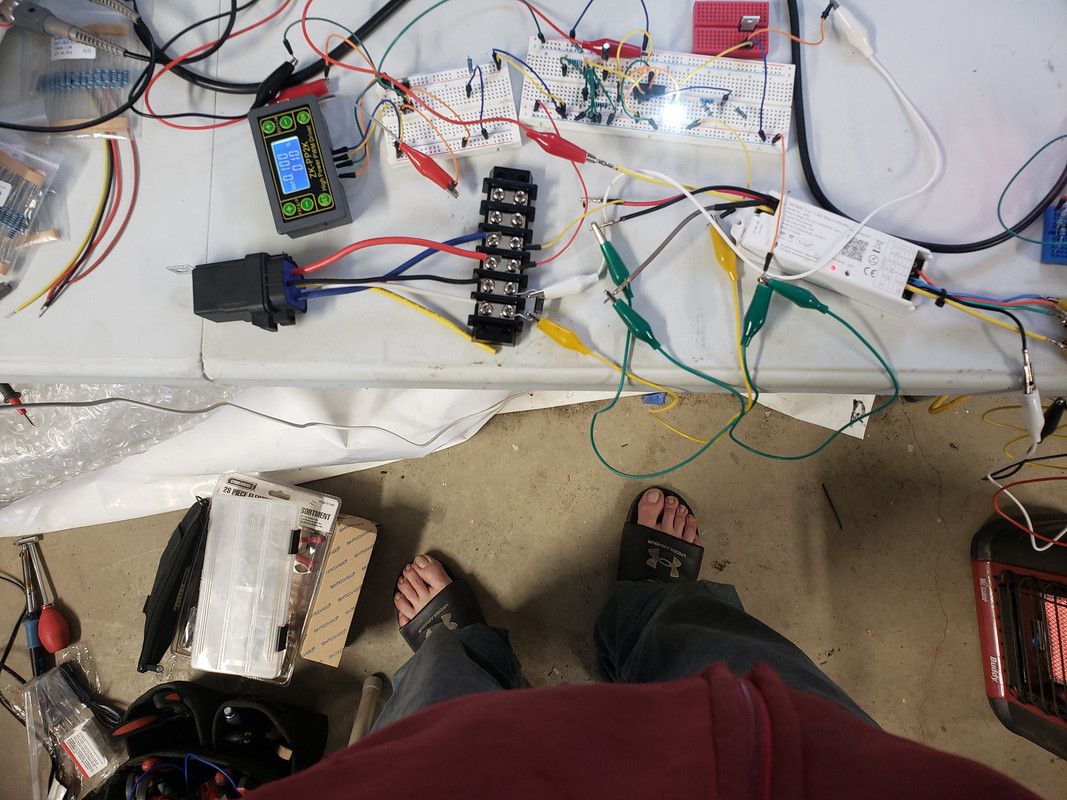
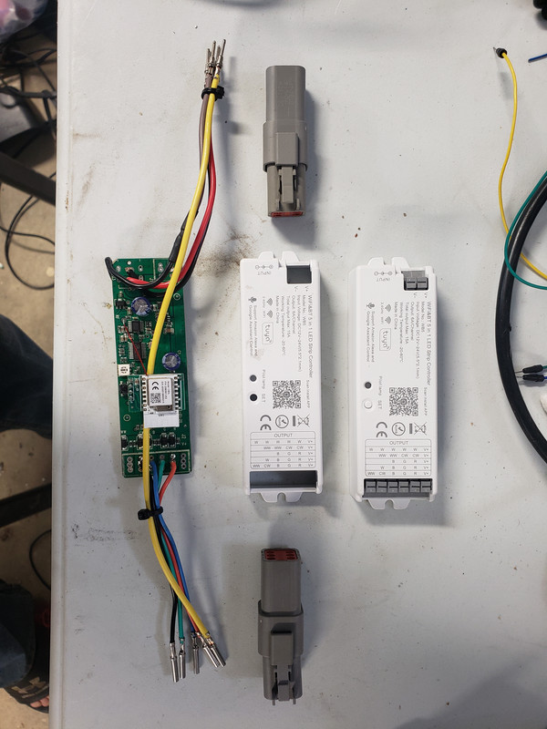
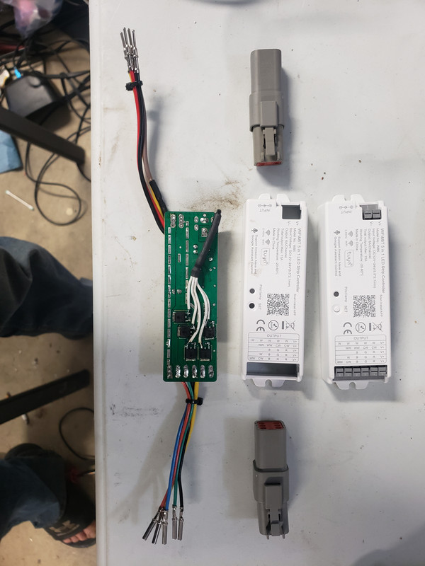
Overall picture, mainly focused on relay to controller power.
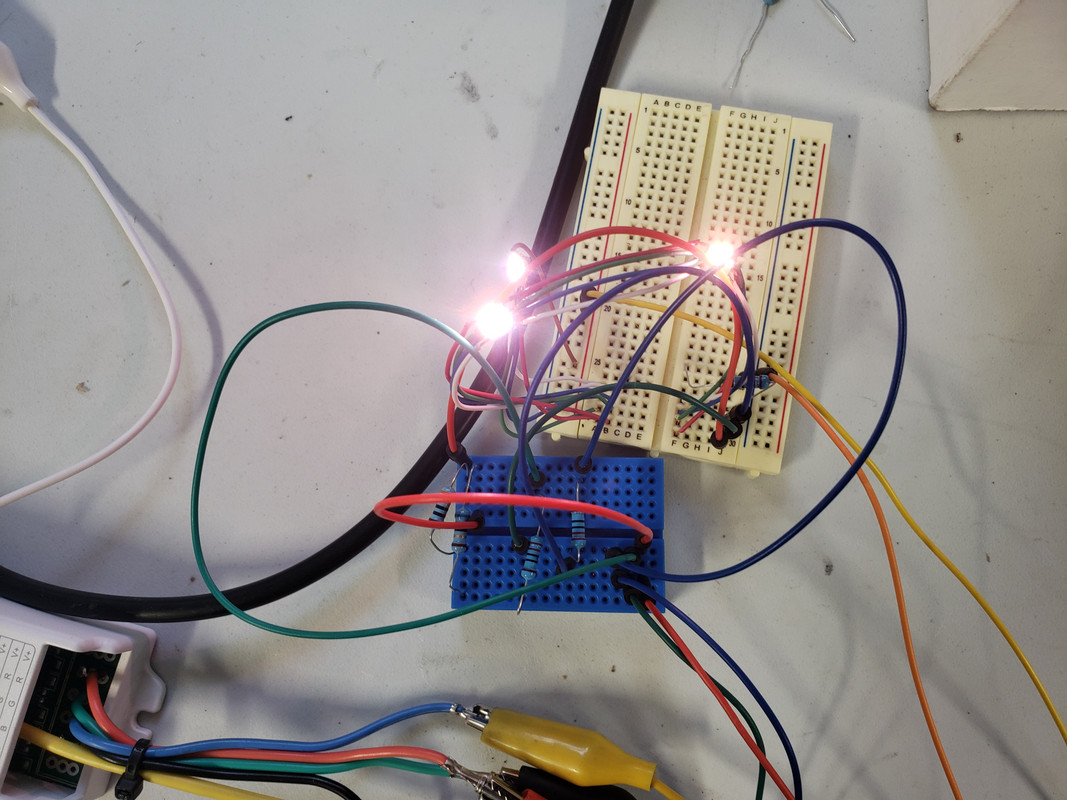
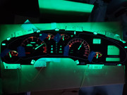
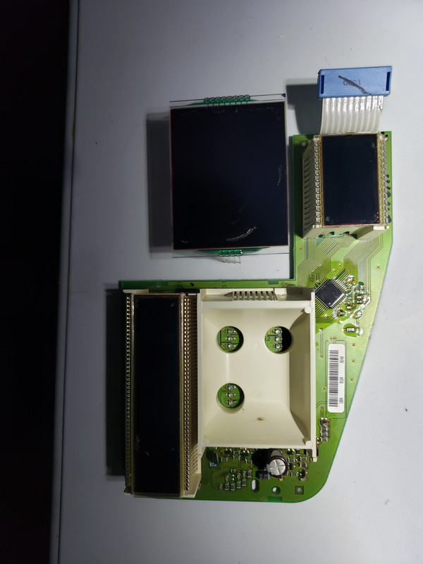
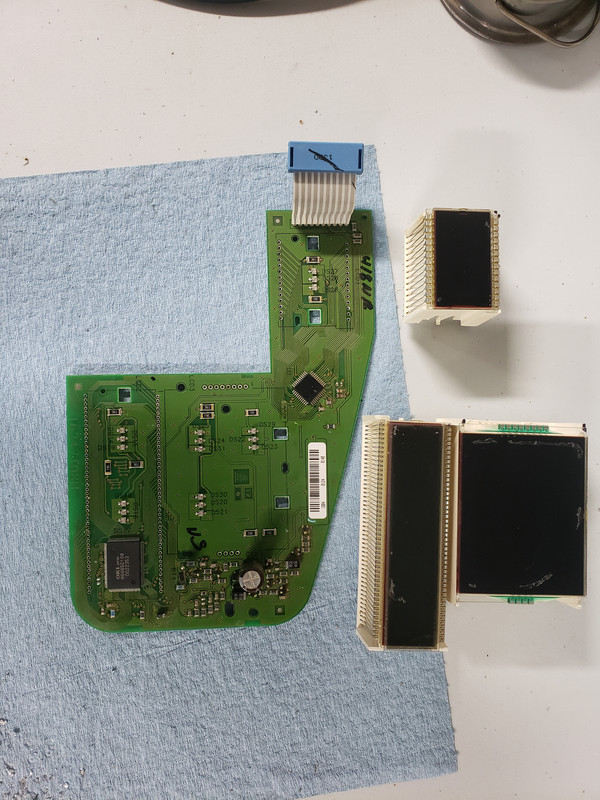
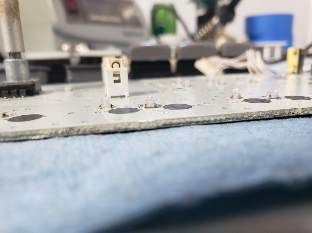
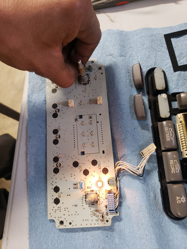
LED assy. Equivalent to an LED strip, just with a custom layout instead of actual strip.
Next step is to get the layout and wire routing figured.
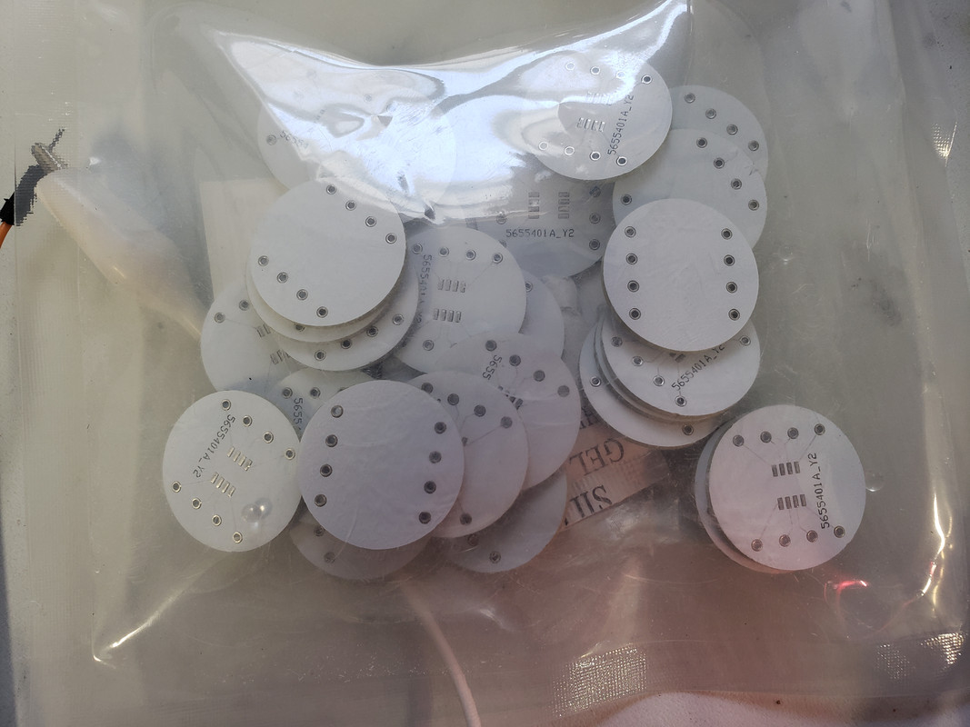
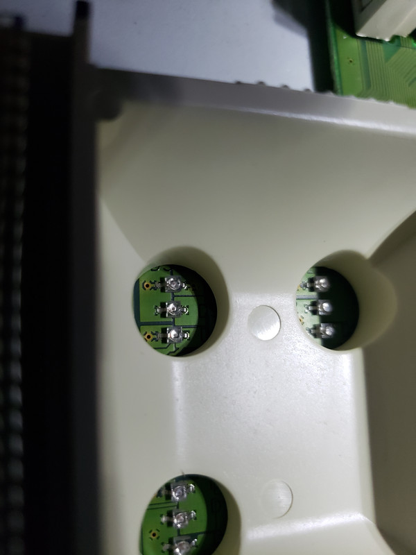
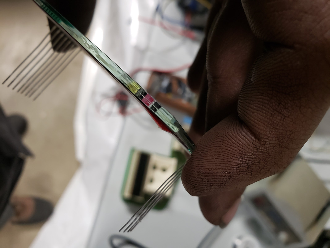
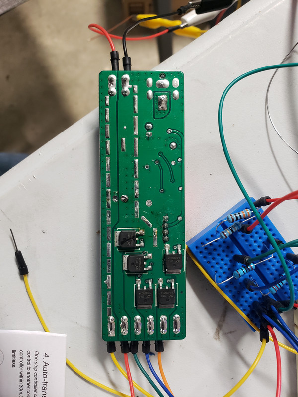
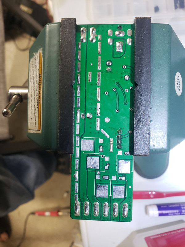
Picture of my test batch of boards. I haven't tested them out yet. I should have put in spots for resistors, but we'll see how it turns out.
I am going to have to get the capacity to make boards I think though. I want faster turnaround for the prototyping phase.