Page 1 of 2
IAT Sensor location
Posted: Sat Jun 28, 2008 1:21 pm
by 99ssei
What is the best location for the IAT sensor?
Closest to the TB or at near the air filter?
I'm replacing the stock accordian tubing with custom tubing for better laminar flow. The tubing does not have a hole for the IAT. My choices are:
a) cut a hole in the tubing just big enough for the sensor and use high temp silicone for a proper seal (use current factory location)
b) buy the 24" extension cable and mount the IAT in the CAI (20$)
c) buy a custom adapter from intense that has a hole pre-molded (located about 1" from TB)
Re: IAT Sensor location
Posted: Sat Jun 28, 2008 8:58 pm
by sonoma_zr2
according to Intense, the stock location is the best. The pcm is programmed for the sensor at that location. It compensates for the higher temp reading internally. You could actually have problems moving it, because it will screw the pcm up with "wrong" temps.
Re: IAT Sensor location
Posted: Sun Jun 29, 2008 3:42 am
by 99ssei
I found this article:
http://www.angelfire.com/my/fan/IAT_sensor.html
Wondering if others who have relocated their IAT have had any problems.
Re: IAT Sensor location
Posted: Sun Jun 29, 2008 11:34 pm
by willwren
I've moved mine around with mixed results. Based on that, I'd suggest moving it to the 'coldest' location possible and let the PCM adapt.
Why?
To prevent the body of the sensor from heatsoaking and affecting your readings long-term. A cooler sensor will give more consistent short-term readings, and allow the PCM to adapt more quickly.
Moving to Performance. This isn't a Forced Induction topic.
Re: IAT Sensor location
Posted: Mon Jun 30, 2008 8:45 am
by 99ssei
I ordered my 24" IAT extension over the weekend.
I'll be drilling a hole and re-locating it in the CAI box (fender side).
Re: IAT Sensor location
Posted: Mon Jun 30, 2008 11:11 pm
by tripscarcare95
You could have just cut and spliced the original wires and extended, be sure to to post pics
Re: IAT Sensor location
Posted: Tue Jul 01, 2008 10:57 pm
by 99ssei
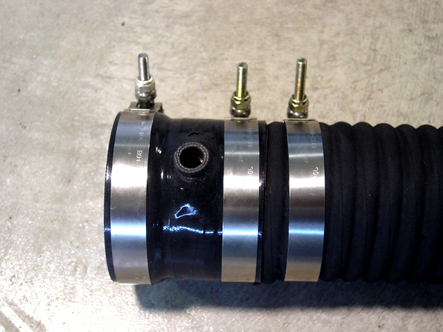
Just installed the 4" tubing (custom) and re-located the IAT sensor in the CAI (cut a 1/2" hole in the fender side of the CAI).
Took it for a test drive...

I'm very happy with the results!!! I'll post pics soon as I can.
EDIT: Had to use jig saw to cut bigger opening in the CAI. (thinking about putting temperature control foil on the inside of CAI....)
Re: IAT Sensor location
Posted: Tue Jul 01, 2008 11:13 pm
by 99ssei
As promised! :-)


EDIT: I put a little white silicone around the IAT to keep it from moving around.
Re: IAT Sensor location
Posted: Tue Jul 01, 2008 11:39 pm
by willwren
I assume you mean 3.5" tubing?
Re: IAT Sensor location
Posted: Wed Jul 02, 2008 8:52 am
by 99ssei
Nope. 4.0" I.D.

Re: IAT Sensor location
Posted: Wed Jul 02, 2008 9:02 am
by sonoma_zr2
willwren wrote:I assume you mean 3.5" tubing?
99 L67 there bud
Re: IAT Sensor location
Posted: Wed Jul 02, 2008 10:41 pm
by willwren
4" ID?
Way overkill, and it's hurting performance. 3.5" INTENSE tubing is the size of choice for a very well-tested and calculated reason.
You may seriously consider dropping that down to 3.5" to produce more laminar flow and velocity.
Re: IAT Sensor location
Posted: Wed Jul 02, 2008 11:08 pm
by 00Beast
Is the TB 4"?? I didn't think they were, and to me, it looks like it is directly on the TB.
Re: IAT Sensor location
Posted: Thu Jul 03, 2008 10:20 am
by 99ssei
I did not see any degradation in performance. It definitely performs better than the stock tubing, though I could not test between the 3.5 and the 4.0 because the 3.5 would not fit over the lip on the TB edge. The opening on the TB is 3.5" however, the lip is about 3.75". Using the 4" tubing, this leaves a .25" gap, however, I used the stock accordion and cut it down to just the ring that fits over the TB lip. I shaved it down enough so the 4" tubing fit over the ring while it was on the TB, then clamped it down for a tight fit.
(side note: installed my scan gauge last night and saw the estimated net horsepower hit 264, 9.5 psi boost, 0.0 KR.)
Re: IAT Sensor location
Posted: Thu Jul 03, 2008 11:59 am
by willwren
Your installation method creates a 'step' at the TB opening which is bad for laminar flow.
I suggest getting a coupler and trying 3.5" like the rest of us do (INTENSE runs all their high-performance cars on 3.5" for this very reason).
Re: IAT Sensor location
Posted: Thu Jul 03, 2008 12:16 pm
by 99ssei
The coupler offered by Intense was $50 + (3) $10 clamps = $80 + shipping.
http://intense-racing.com/pics/fwi/fwi_ ... _large.jpg
I paid = $0
In addition, the Intense coupler puts the IAT right next to the TB, which is bad because of heat soaking.
((doesn't want to be like everyone else))
Re: IAT Sensor location
Posted: Thu Jul 03, 2008 12:36 pm
by willwren
You don't have to use the INTENSE coupler, and you don't have to put the IAT there (I didn't).
http://www.siliconeintakes.com/
Don't feel bad for being like everyone else. INTENSE made the dimensions that way for a very well-proven reason. Too big is just as bad as too small.
Re: IAT Sensor location
Posted: Thu Jul 03, 2008 12:41 pm
by 99ssei
Where can I find these "very well-proven reasons?"
Re: IAT Sensor location
Posted: Thu Jul 03, 2008 12:48 pm
by willwren
http://www.intense-racing.com/inno.shtml
And every record they broke with that 3.5" FWI installed. Including more recent records not shown on that page.
Re: IAT Sensor location
Posted: Thu Jul 03, 2008 12:54 pm
by 99ssei
That's great info.....however, that doesn't answer the question:
Where can I see "very well-proven reasons" why the 3.5" ID tubing is better than the 4.0" ID tubing?