Originally Posted: Jan 28, 2007
Ok, another week gone by, time for a status update.
The crank, rods, pistons, harmonic balancer, and flex plate are now at Express Engines in DeLand, Florida to be balanced as an assembly. The local machine shop in Holly Hill didn't have bob weights that fit the V6 crank, so it had to go to a different shop.
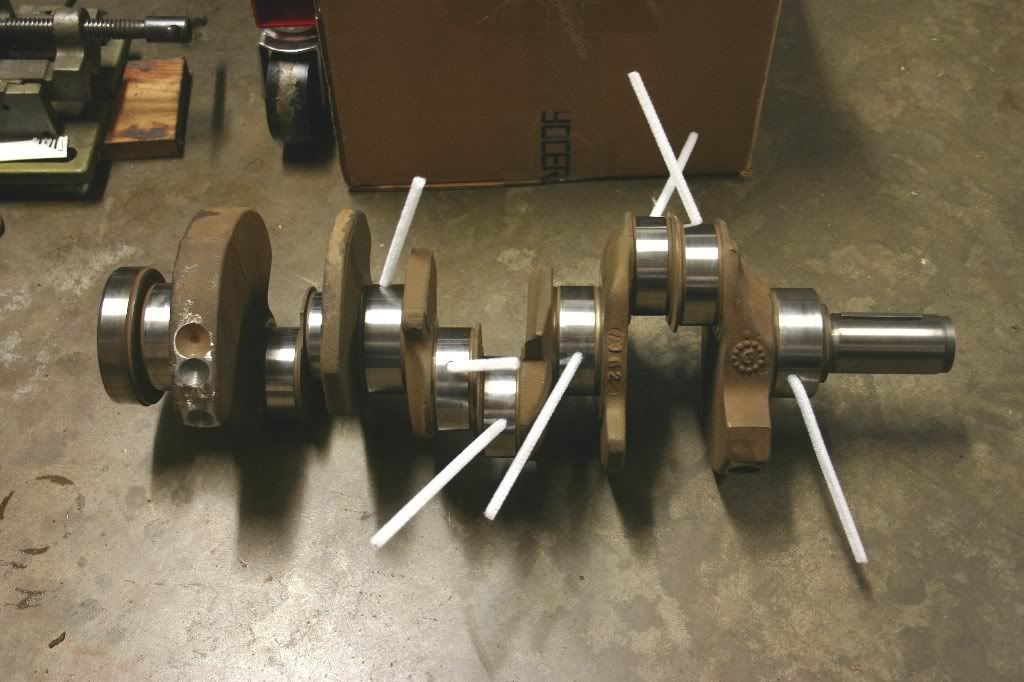
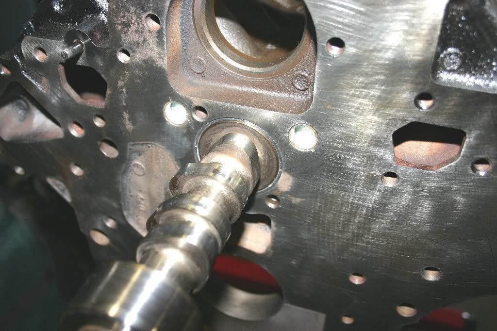
While waiting, I can still do some work on the camshaft and the block. Here's the camshaft along with the other timing components.
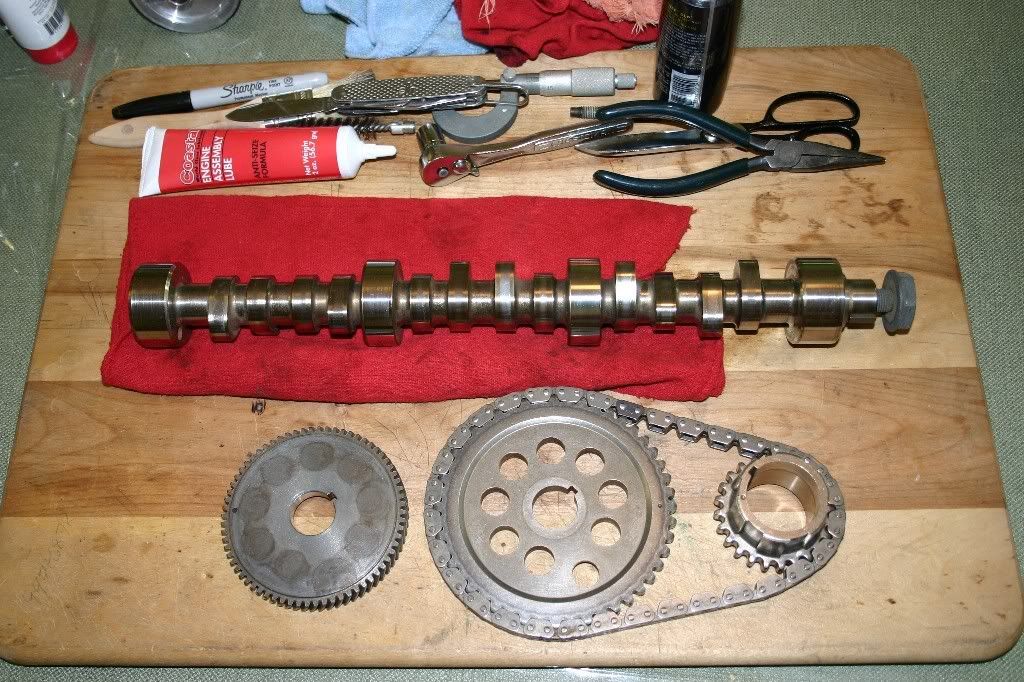
The cam appears to be a billet steel cam (meaning it was cut from a single chunk of steel rod stock as opposed to being machined from a cast iron core. In the photo, from left to right are #4 Cam Journal, #6 Exhaust Lobe, #5 Intake Lobe, #6 Intake Lobe, #5 Exhaust Lobe, #3 Cam Journal, #4 Exhaust Lobe, #3 Intake Lobe, #4 Intake Lobe, #3 Exhaust Lobe, #2 Cam Journal, #2 Exhaust Lobe, #1 Intake Lobe, #2 Intake Lobe, #1 Exhaust Lobe, and #1 Cam Journal. It's the geometry of the motor that dictates the placement of the lobes on the cam.
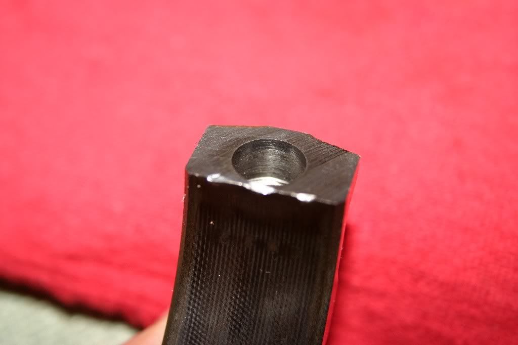
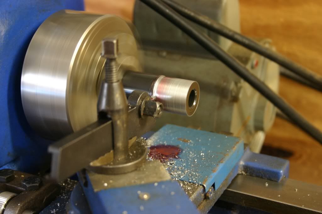
Looking a little closer at the cam, here's the back end. Note the three holes. Two of them are left over from the manufacturing process and only one serves a real purpose inside the motor.
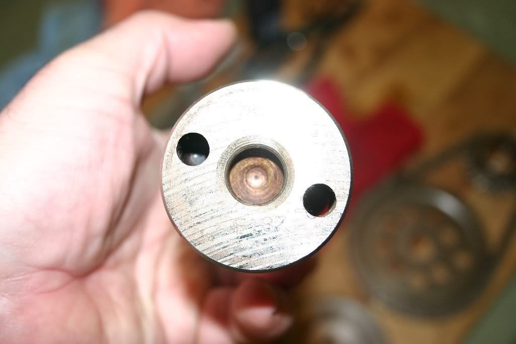
The center hole is a lathe "Center". It's a machined pocket that fits a dead center in the drive face of the lathe. To the left of it is a hole that fits a pin in the face of the lathe (called a drive dog) that will index the cam on the equipment. The hole on the right is also used during manufacture for a second drive dog, however it is drilled through the #4 journal. When the cam is in the motor, this hole serves as a relief to keep oil pressure from building up between the cam and the plug/cover that seals up the bell housing end of the block. Without that hole, oil pressure would build up and pop the cover.
Cams are made on duplicating (or Pantograph) lathes and grinding machines. In the process, the work piece (i.e. the yet to be made camshaft) is being spun by the lathe while a pattern is being spun at the same speed, parallel to the work piece. The cross-head (with the cutting bit) follows the pattern and transfers it to the work piece. It take 10 different patterns to cut and grind the cam to it's finished form, so the index holes in the end of the cam keeps everything in sync with the patterns as the cam moves from step to step. If you are ever in Daytona Beach during race weeks, drop in on Crane Cams and you can usually get a tour of the plant to see them making cams.
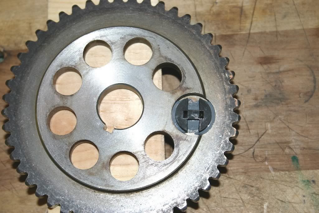
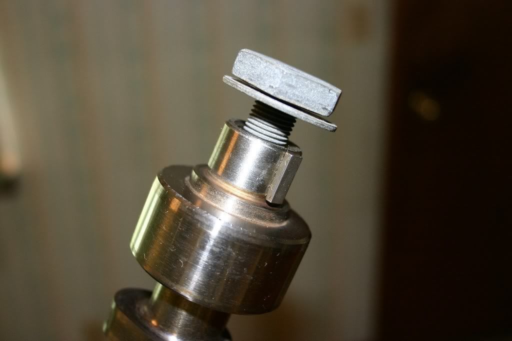
Back to this cam... Here's the timing chain end of the cam. Unlike most cams, the Buick V6 uses a key in the snout to drive the cam...same thing used on the crank nose to drive the oil pump and balancer. The reason for this is the Balancer shaft drive gear that also uses the cam. It's easier to slot the end of the cam for a key and broach the timing gears. The alternative is a whacky pin and bolt arrangement.
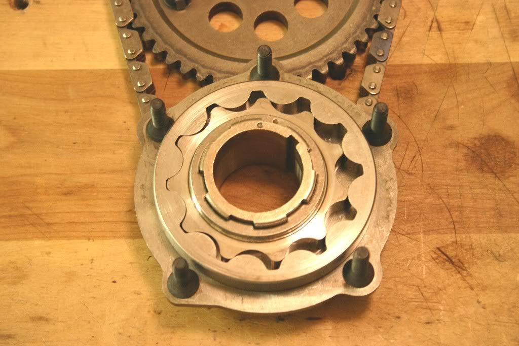
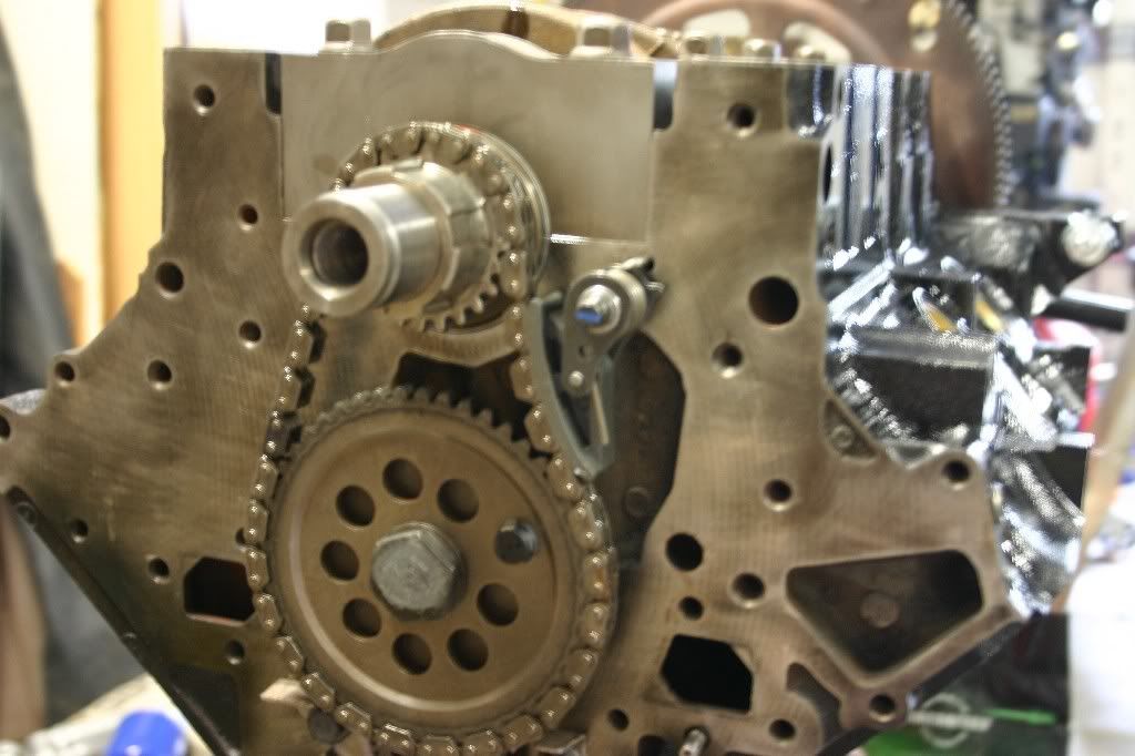
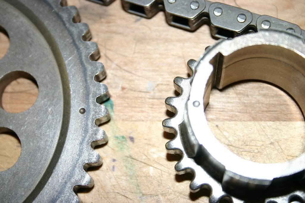
Here's the timing chain and its gears. Note the dimples in both the cam gear and the crank gear. When the set is installed, the dimples with be lined up with each other. That times the crank rotation with the cam rotation. The geometry of the motor comes into play again. The cam gear has twice the teeth of the crank gear, so the cam will always spin at 1/2 the crank RPM.
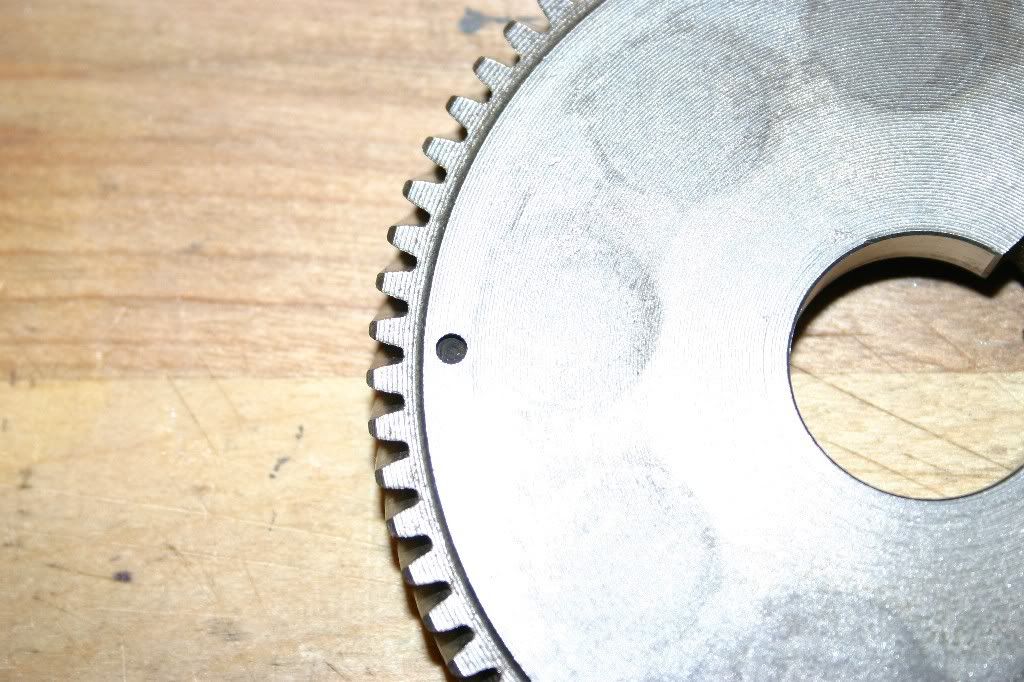
Here's the drive gear for the balancer shaft. It has a dimple on it as well to line up on the gear on the end of the balance shaft, so it spins in time with the crank.
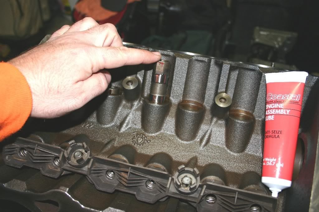
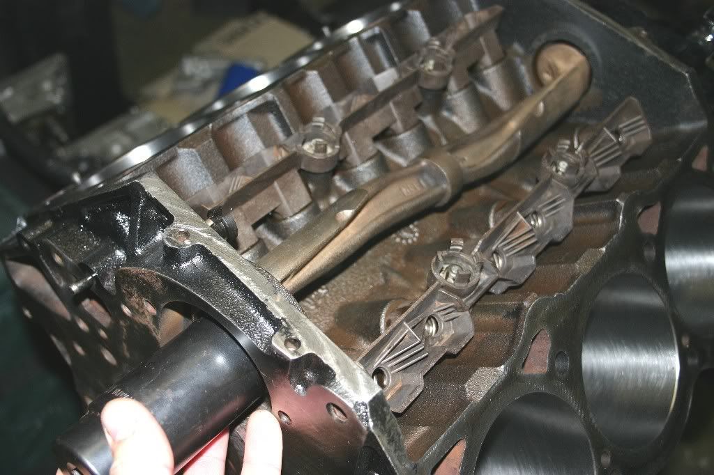
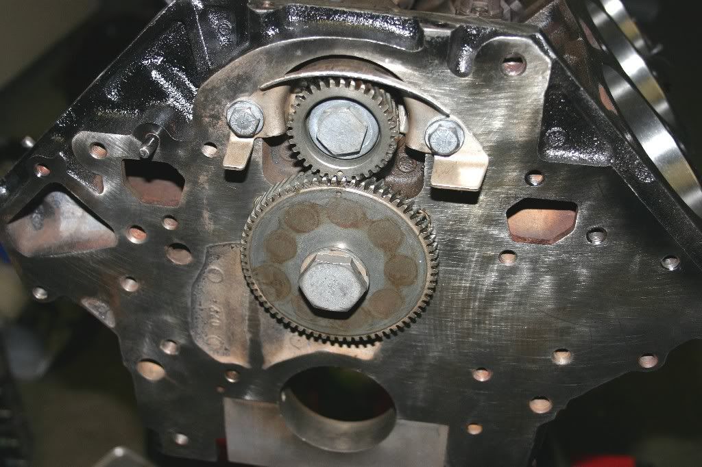
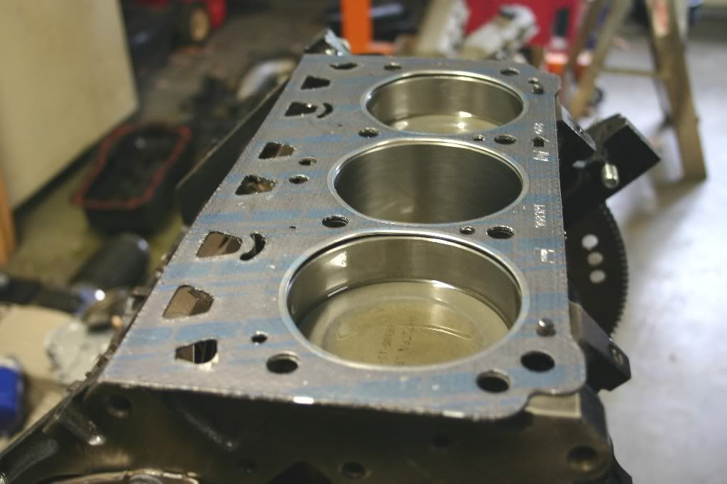
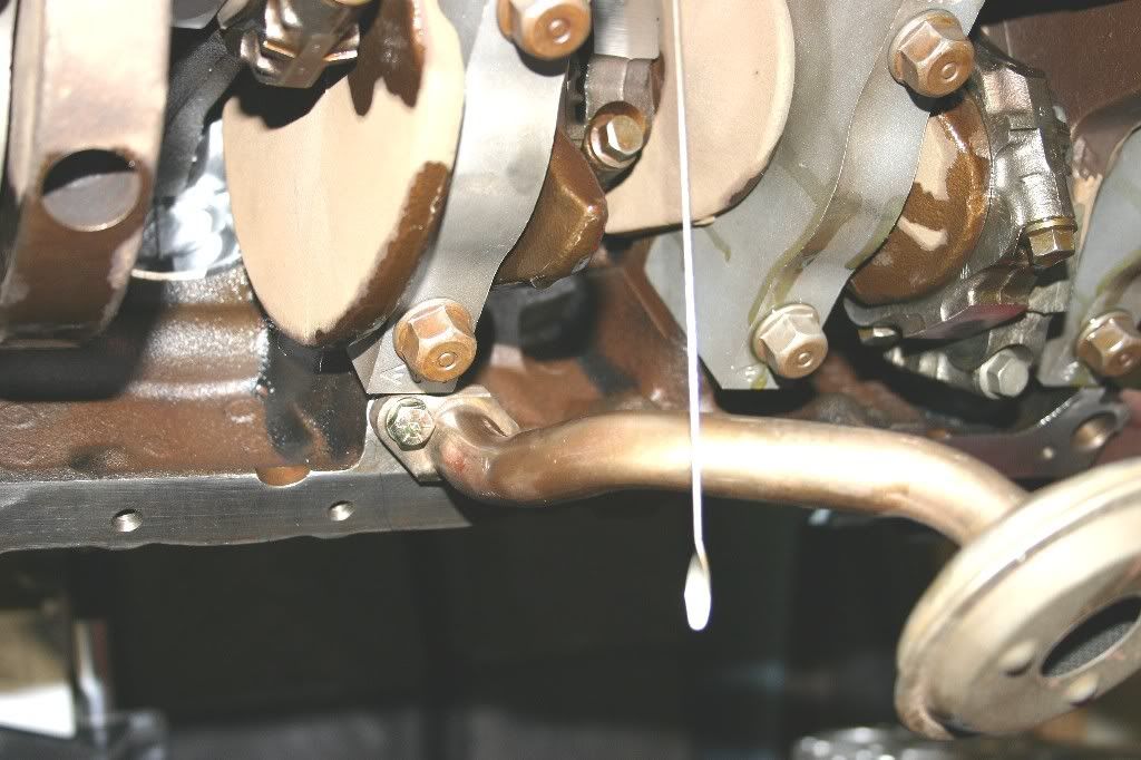
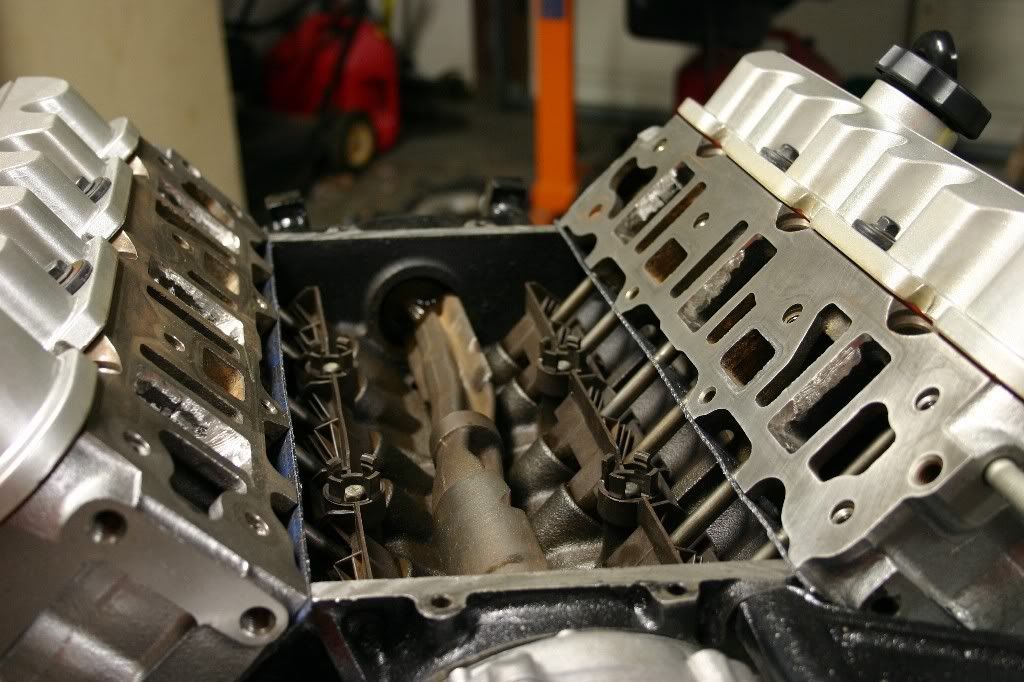
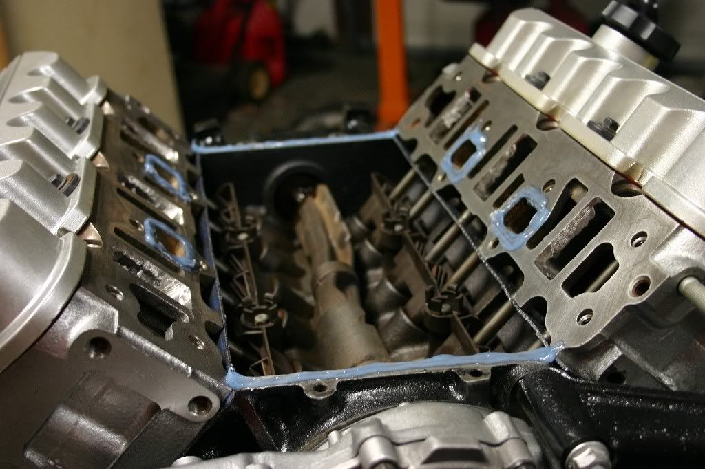
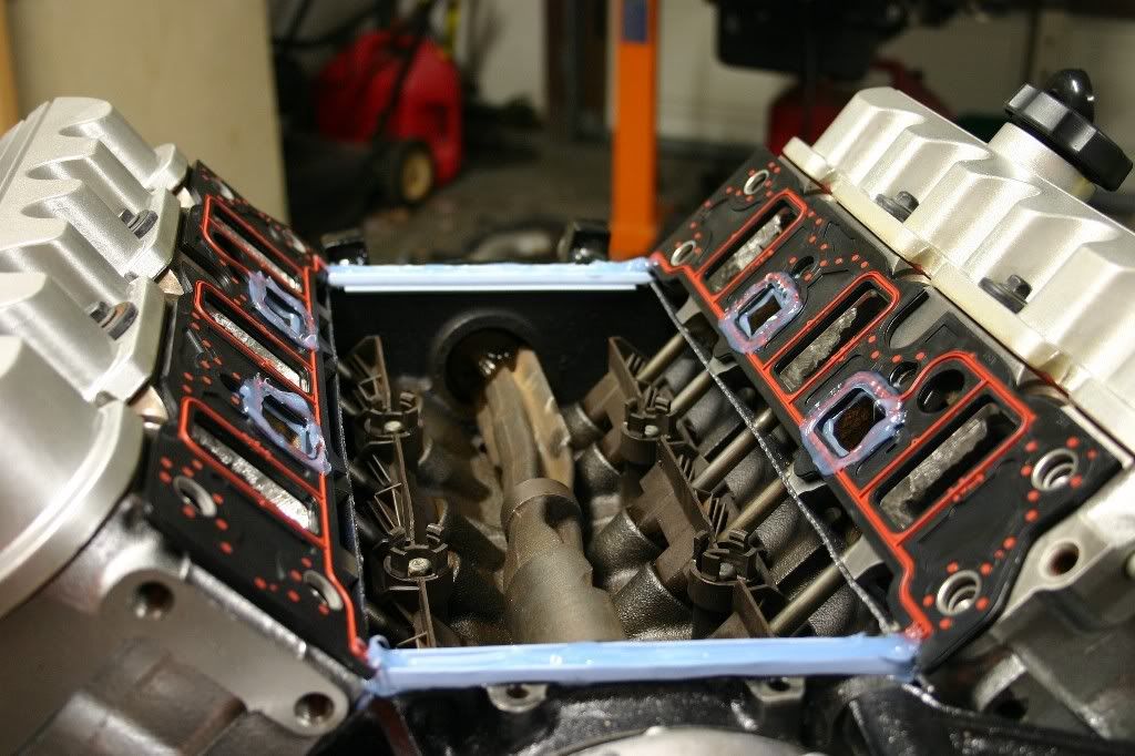
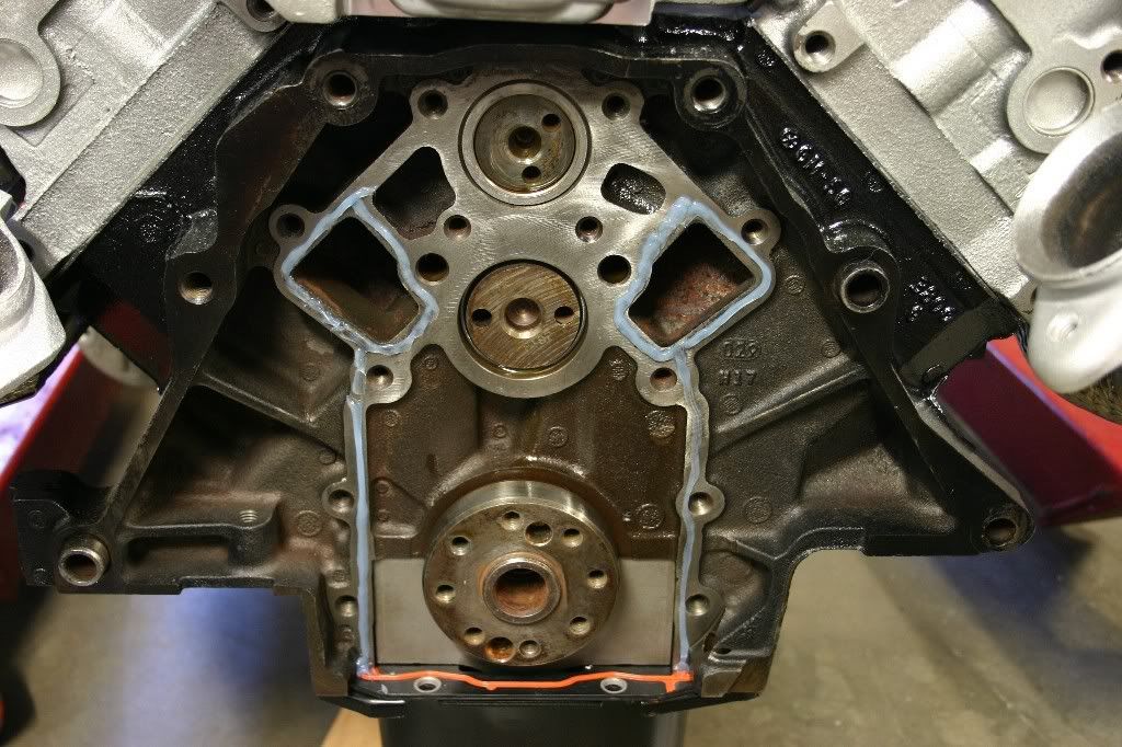
Time to put some stuff back inside the engine block. First item to go back in is the camshaft. It was the last item to come out because it is easiest to remove that way. It's the first to go back in for the same reason. Use some engine assembly lube on the journals and on the bearings, then carefully slide the cam in. Stick your finger up inside the block to support it as it slides in. (The cam bearings are new, no sense screwing them up by gouging them with cam lobes.)
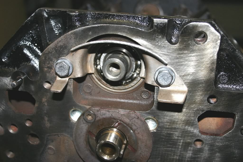
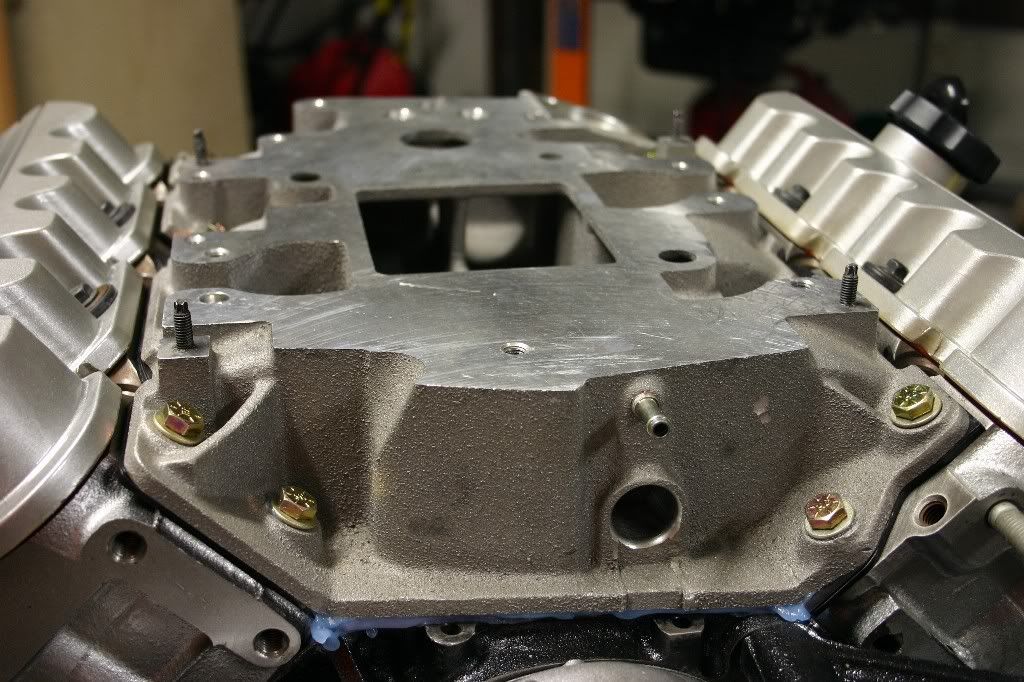
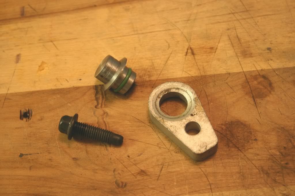
Next up is the cam retainer plate and its screws. Again, apply a little assembly lube to both faces and install. Torque the #30 Torx screws to 11ft-lbs. The purpose of this plate is to keep the camshaft from walking fore-aft in the block. The plate is trapped between the shoulder of #1 cam journal and the back of the balancer shaft drive gear.
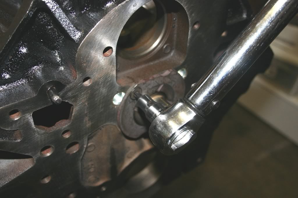
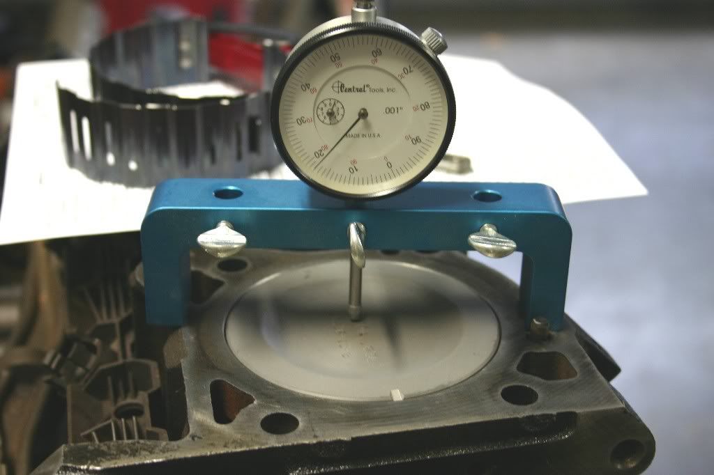
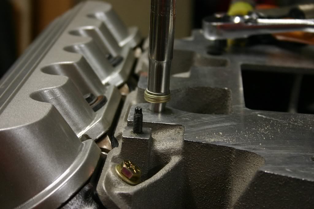
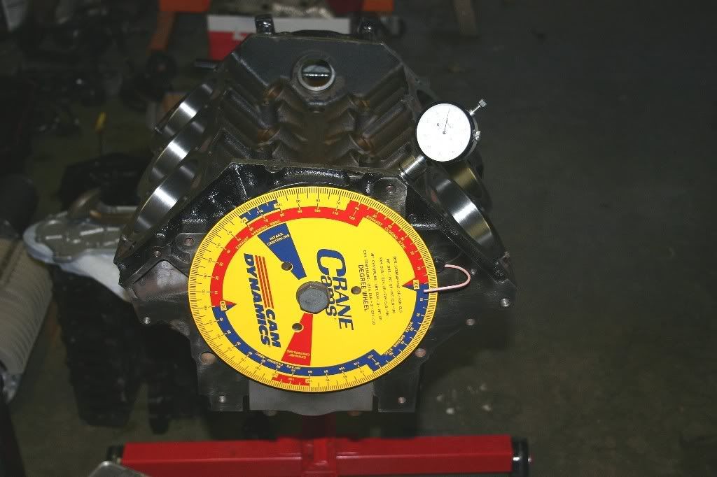
Ok, gears go on next and then a degree wheel is temporarily installed on the nose of the cam. (Note: A degree wheel is usually done on the crank nose, but since I know the block centerline and have the dimple on the cam gear to reference, I can get a profile of the cam lobes without the crank.)
The pointer (pink wire in photo) is just a chunk of coat hanger wire bolted to the block.
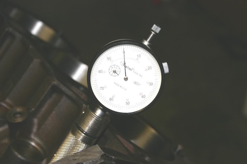
A dial gauge is in the lifter bore with its tip riding on the cam lobe. In the photo it's the #1 Exhaust lobe. Now, the tedious task of rotating the cam and recording the reading on the dial gauge. Again, because the degree wheel is on the cam, the markings on the degree wheel need to be doubled to represent the crank rotation...in other words, 10 degrees of cam rotation is equal to 20 degrees of crank rotation.
With that done, here's the plot of the cam's profile:
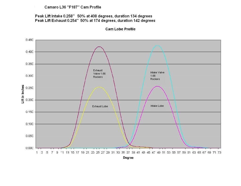
The valve lift numbers are computed with a 1.66 rocker arm ratio. (I need to mock one up to see if that is the actual ratio of the rockers.)
Next, I need to do the same thing to the stock L67 motor to see what its cam grind looks like.
I sat down with a calculator and figured out the "Grind Card" for the cam (for comparative purposes to other cams.)
Intake: opens 24 degrees ATDC, 191 degrees duration @ 0.050", lobe lift 0.258"
Exhaust: opens 6 degrees BBDC, 194 degrees duration @ 0.050", lobe lift 0.254"
Lobe separation angle 115 degrees.
The lobes are asymmetrical (dual pattern grind)
Bye Bye 1990 Bonneville LE... Now it belongs to my daughter
In the Garage: 2009 Subaru Outback, 1987 Camaro, 2006 SV650S, 1995 Regal 182 "ASANAGI", 1962 Ford Galaxie 500, 1995 Ford F150 XL 4WD, 1953 Farmall Cub