It is currently Sat May 04, 2024 2:32 am

All times are UTC - 5 hours [ DST ]


Post new topic Reply to topic  [ 35 posts ]  Go to page 1, 2  Next
Author Message
PostPosted: Sat May 24, 2008 10:01 am 
Offline
Retired Gearhead
Retired Gearhead
User avatar

Joined: Tue May 20, 2008 9:11 pm
Posts: 2156
Location: Fayette City,PA
Year and Trim: 1990 Bonneville LE
Originally Posted: Dec 31, 2006

Figured I would document this process for anyone who might be interested.

I'm starting with a 1996 Series II 3800 from a Pontiac Firebird (RPO Code L36). Purchased for $100. I'm not getting into the rational of why this is being done (please, none of the usual "you should go out and buy a L67.." stuff.) My intended purpose is to show anyone who may be interested what is actually inside the motor and how to take it apart and reassemble it, with some selective part substitution along to way to reconfigure it to a supercharged motor.

So, here's day one: The motor was partially disassembled when it was picked up, so there's not a lot to show taking off the intake manifold. The heads are easily removed, a 9mm socket is used to remove the rocker arms, while a 9/16th socket is used to remove the main cylinder head bolts. There are only two lengths..8 short bolts along the flange on the outside of the motor (4 per side) and 8 long bolts inside the valve cover area (again, 4 on each side.) I'll cover the cylinder heads in a little bit.

Image

On this motor, the previous owner had loosened the head bolts before draining the coolant. The end result is the orange sludge showing inside cylinders 2 and 4 in the photo. While a dumb thing to do, it could have been worse. Had it been water left in the bores, it would have destroyed the cylinder walls and required an immediate overbore and larger pistons.

As it is, this motor will need to be disassembled to remove the rods and pistons and will probably need to have a new set of piston rings fitted at minimum.

Some differences between the RWD and FWD motors are evident as well. Note the position of the oil filter boss. That will need to be removed and replaced with one from a FWD 3800. Also note the oil pan shape, it has relief areas pressed into it for the F-Body K-Member and exhaust manifold Y-pipe.

As to mounting the motor on an engine stand. You will need 12mm x1.75 bolts to connect the engine stand to the block. I'm using a mix of 90mm, 100mm, and 120mm bolts to do the job. Flat washer are also needed to keep the motor level on the stand, as bottom left transmission bolt (when viewed fro the rear of the motor) is set up with a locating dowel. The washers make up for the lack of the dowel on the other side of the motor.

_________________
Bye Bye 1990 Bonneville LE... Now it belongs to my daughter
In the Garage: 2009 Subaru Outback, 1987 Camaro, 2006 SV650S, 1995 Regal 182 "ASANAGI", 1962 Ford Galaxie 500, 1995 Ford F150 XL 4WD, 1953 Farmall Cub


Top
 Profile  
 
PostPosted: Sat May 24, 2008 10:02 am 
Offline
Retired Gearhead
Retired Gearhead
User avatar

Joined: Tue May 20, 2008 9:11 pm
Posts: 2156
Location: Fayette City,PA
Year and Trim: 1990 Bonneville LE
Originally Posted: Dec 31, 2006

Quote:
MOS95B wrote:
The pic above perfectly illustrates why everyone yells "Drain that oil!!" as soon as someone suspects a UIM failure. Looks nasty already, don't it? Imagine letting it sit for a while.


Exactly, but there's a better illustration yet to come....

So, with the heads off, it's time to start taking down the front of the block, starting with the water pump. Here is the front of the motor and the 4 8mm bolts holding the pulley on. If you happen to have the accessory drive belt on and with tension, it's pretty easy to remove them. Without a belt, use a box wrench and a rubber mallet to loosen the bolts. (A quick, accurate, whack on the end of the wrench will pop the bolt loose with just your hand holding the pulley still.) Note, while the bolts are marked metric 8mm, I found that they are a bit undersize. An SAE wrench fit the heads better (tighter to the flats.) You run across this a lot in mass produced bolts. Just because it is supposed to be metric, doesn't mean that an SAE sized wrench might fit the actual head better. Don't be afraid to use the wrench that fits best, regardless of the markings.

Image


OK, water pump pulley is off and in the pile of parts to be cleaned. Next stop, the water pump itself. Note how clean it looks...it's almost certain to be a replacement part. This is actually a good thing, its seals look good and the impeller spins smoothly with a little bit of drag. Previous owner probably though the coolant leak was because of a bad pump and replaced the wrong part. His loss is my gain (little payback for him screwing up the cylinders.)


To take the pump off, there are two SAE bolt sizes used around the perimeter of the pump. Don't worry, you can't screw up and confuse them on reassembly as the larger ones are long enough to pass through the timing cover and into the block.


Image

Image


OK, pump is off, need to make a little working room around the harmonic balancer. So the oil filter boss/oil pressure sensor plate needs to come off. No sweat, 4 SAE bolts of identical length are used to hold it on. Once out, a little tap with the rubber mallet will unseal it from the block. Don't go overboard, there’s two loose parts inside that you don't want to loose.

Image


Oh H***. Inside the cover looks like a mess. That nougat looking crud dripping out of the oil cavity is a mixture of Dex-Cool and Oil. This means that the entire block needs to be stripped down and cleaned, as this goop is inside the oil passages in the block, and may be in the bearings as well. Only way to be sure is to strip the block down and inspect the parts.

Image


Now for the real fun. The one bolt torqued to a gazillion ft-lbs. is the harmonic balancer bolt. To get that monster out, you need either the Air Impact wrench from h***, or a 4-foot or longer breaker bar. Either way, the crank has to be locked down to keep it from moving. The easiest way of doing this is to put the flex-plate on, then slip a steel drift punch through one of the Torque Converter mounting holes. Rotate the engine until the drift is wedged tight against the starter mounting pad on the block, and the engine stand. That will lock the crank in place while you wail on the harmonic balancer bolt.

Image


Once the "Bolt-From-H***" (tm) is out, a Harmonic Balancer puller is used to draw the balancer off the crank nose. This one came off quite easy, though a deep socket had to be inserted into the crank nose to give the puller something to work against (Mine is a typical V8 style puller.)


Image


Balancer off, lip seal and crank nose look good. Note the splash shield around the reluctor sensor. This is a plastic piece that just pops off the three studs with a little prying with a screwdriver. I don't know if this piece will fit older 3800's, but it's worth looking into. (If you've ever flooded the crank sensor on your Bonneville, then you know first hand how well they don't work if the get wet )

Image


Ok, down to the timing cover. This is a good place to pause. The next part to come off will be the oil pan as a prelude to removing the timing cover.

_________________
Bye Bye 1990 Bonneville LE... Now it belongs to my daughter
In the Garage: 2009 Subaru Outback, 1987 Camaro, 2006 SV650S, 1995 Regal 182 "ASANAGI", 1962 Ford Galaxie 500, 1995 Ford F150 XL 4WD, 1953 Farmall Cub


Top
 Profile  
 
PostPosted: Sat May 24, 2008 10:13 am 
Offline
Retired Gearhead
Retired Gearhead
User avatar

Joined: Tue May 20, 2008 9:11 pm
Posts: 2156
Location: Fayette City,PA
Year and Trim: 1990 Bonneville LE
Originally Posted: Sun Dec 31, 2006

Quote:
jr's3800 wrote:
Very Nice Curt.. Interested to see the process


Here's some more....

I forgot to photograph the Harmonic Balancer coming off, so I hopped over the 2000 L67 and pulled its balancer...

Procedure has been described before on the forum, use three M6-1.00 bolts with 1/4" fender washers. In my case, the bolts are 70mm long. I also had to use a deep socket inside the crank nose to give the puller something to push against. (Mine isn't long enough to reach the bottom of the hole on its own.)

Image


Ok, with the balancer off, time to get some stuff out of the lifter valley and mark the pistons before turning the block over to remove the oil pan.

Here's the lifter valley, the balancer shaft runs up the middle. On either side is the row of roller rockers and the plastic retainers that keep them running straight in the bores. Take the four bolts out and remove the two lifter retainers:

Image


Now with the retainers off, time to pull the lifters out of the bores. Note more of the oil/coolant spooge in the tops of the lifters. The tool in the photo (attached to the #3 cylinder lifter) is a gizmo for pulling lifters. It goes into the top of the lifter, tightens to expand the tip, and hooks the clip slot in the top of the lifter body (more on this later when we take apart the lifters for cleaning.) Built into the tool is a slide-hammer to tap out the stubborn lifter.

Image


Here's a better snapshot of the entire tool attached to the lifter being pulled

Image


Finish removing all 12 lifters and set them aside to be cleaned and inspected later.

Now, here's an important step. You need to mark every piston part BEFORE you remove them from the bores. You also need to mark them in a way that you can install them correctly, not upside-down. The reason is simple. Every piston is made with a thrust side and is supposed to be installed facing a particular way relative to the direction the engine rotates. Once the new pistons are in and running, they wear a little to match the bore they were installed in. On installation, the piston needs to be installed in the same bore it came out of, and facing the same direction.

The best way to do this is to punch a number into each piston crown. I am also going to punch the same number into the rod and rod cap in a little while, but doing the crowns now with the motor right-side up is easier.

I may end up replacing the pistons and rods later. A big part of that decision will be the condition of these pistons once they are out, cleaned, and inspected. Cardinal rule of engine rebuilding: Never throw anything away until you are certain it's bad AND you have the replacements installed. (even if these prove to be junk, you still need to take some measurements off them for replacements.)

My daughter Carolyn took over camera duty while I stamped the pistons...

Image


And here's the #2 piston crown with the "2" clearly stamped into the crown at the top.

Image


Ok, that’s it for today. We'll pick up tomorrow with the motor flipped over for removing the oil pan. Time to get cleaned up and celebrate a new year.

Happy New Year Y'all !!!

_________________
Bye Bye 1990 Bonneville LE... Now it belongs to my daughter
In the Garage: 2009 Subaru Outback, 1987 Camaro, 2006 SV650S, 1995 Regal 182 "ASANAGI", 1962 Ford Galaxie 500, 1995 Ford F150 XL 4WD, 1953 Farmall Cub


Top
 Profile  
 
PostPosted: Sat May 24, 2008 10:44 am 
Offline
Retired Gearhead
Retired Gearhead
User avatar

Joined: Tue May 20, 2008 9:11 pm
Posts: 2156
Location: Fayette City,PA
Year and Trim: 1990 Bonneville LE
Originally Posted: Jan 02, 2007

Quote:
harofreak00 wrote: those number punches look fun


They come in quite handy, as we are about to see...

Here's the victim upside-down for removing everything up through the crank. First item to remove is the oil level sender (Tan-looking Hex Nut in the side of the oil pan. Be gentle, it's just plastic and it isn't threaded very tight.) You need to take it off because it sticks through the pan and into the baffle inside.


Image


Now time to take off the oil pan. Remove the twenty bolts that hold it on. Don't worry about mixing these up, they are all identical in size and length. Just dump them in a plastic bag to be cleaned later.


Image


Pan is off...more of that Dex-Cool and Oil "milkshake" showing. Note, the oil pan gasket also doubles as the windage tray/baffles for the oil pan itself. Take it off and discard it.

Image


Next remove the oil pump pickup (two 8mm head bolts) and just pop it off the gasket on the block oil pan rail.

Time to start taking out the pistons. Again, I am punching numbers into the rod caps and the rods themselves to keep the pairs together. There's a machined flat on the rod side where you can punch the numbers. Keep the bearing shells with the rods for later reference (just because they are worn, you should still measure them for replacements...just in case one of the mains was previously machined undersized.)


Image


Here's the #1 crank journal with the rod removed. The spooge is all the way down into the bearing surface and the cross-drilled oiling feeds inside the crank. Also, you can better see the reference numbers stamped into the rods (on #2 cylinder)


Image


When removing the pistons, be careful not to scratch the crank journal. When I'm doing them. I use a drift punch in one of rod holes to carefully guide the rod away from the crank and down the piston bore. Remove the caps while the piston is at BDC, then rotate the crank 180 degrees to shove the piston to TDC, then guide it the rest of the way out of the bore (get you hand under the piston to catch it. The bores in this motor were not worn and the tops didn't need to be ridge-reamed to get the pistons out...they just slid right out.


Image


Ok, here's the six pistons. Initial inspection shows they are all in usable condition. After they are cleaned up, we'll be checking them closer to see that this is true.


Image


I'll pause the narrative here. When we pick up a little later, we'll be taking the timing cover off and removing the crankshaft main caps.

_________________
Bye Bye 1990 Bonneville LE... Now it belongs to my daughter
In the Garage: 2009 Subaru Outback, 1987 Camaro, 2006 SV650S, 1995 Regal 182 "ASANAGI", 1962 Ford Galaxie 500, 1995 Ford F150 XL 4WD, 1953 Farmall Cub


Top
 Profile  
 
PostPosted: Sat May 24, 2008 10:51 am 
Offline
Retired Gearhead
Retired Gearhead
User avatar

Joined: Tue May 20, 2008 9:11 pm
Posts: 2156
Location: Fayette City,PA
Year and Trim: 1990 Bonneville LE
Originally Posted: Jan 02, 2007

Quote:
BillBoost37 wrote:
Curt...being that you brought it up..please explain the ridge reeming and why it would need to be done. (carbon buildup)


Sure,

As the engine wears, a ridge forms at both the top and bottom of the cylinder walls. The ridges are where the rings stop moving as the slide up and down with the pistons in the bore.

If the engine has a lot of wear, the ridge will be pretty deep and will bind the piston rings together as you try to remove it (worst case being breaking the rings and damaging the piston. )

An inexpensive tool, called a "Ridge Reamer" fits into the top of the cylinder and scrapes off the carbon as well as the iron bore to remove the ridge. It's kind of like an apple-peeler inside-out: the blade presses against the inside of the cylinder wall and removes the raised metal of the ridge. The carbon isn't usually a problem, but an iron lip at the top of the cylinder is going to be a problem the ridge reamer will take care of. In the case of this motor, with 100K on it (according to the original owner) the ridge is practically non-existent, so no special work needed to be done before removing the pistons from the bores.

The ridge reamer, piston ring compressor, valve spring compressor, and harmonic balancer puller are the only specialty tools needed on this motor. Everything else can be accomplished with common hand tools.

There's a few additional items, but they are block prep items that any machine shop will have and use to get things like the cam bearings installed. As with any project, there are limits to what most people can do...then there are some things that the home user should NOT do. For example, unless you have a few thousand in spare cash laying around, you will not have the machine tools to over bore blocks, surface grind decks, weld/grind cranks, etc. These are tools that machine shops already own along with the experience to use them correctly. So at some point in this project (like Tomorrow!) the block will get carted off to the machine shop to be hot-tank cleaned and new cam bearings installed. The shop fees are usually quite reasonable and there's a strategy to dealing with them I'll get into a little later.

_________________
Bye Bye 1990 Bonneville LE... Now it belongs to my daughter
In the Garage: 2009 Subaru Outback, 1987 Camaro, 2006 SV650S, 1995 Regal 182 "ASANAGI", 1962 Ford Galaxie 500, 1995 Ford F150 XL 4WD, 1953 Farmall Cub


Top
 Profile  
 
PostPosted: Sat May 24, 2008 11:02 am 
Offline
Retired Gearhead
Retired Gearhead
User avatar

Joined: Tue May 20, 2008 9:11 pm
Posts: 2156
Location: Fayette City,PA
Year and Trim: 1990 Bonneville LE
Originally Posted: Jan 02, 2007

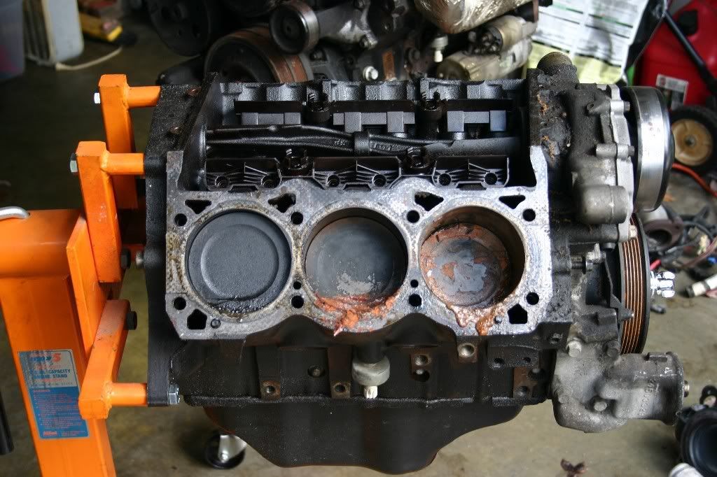
Picking up where I left off... Timing chain cover comes off next.

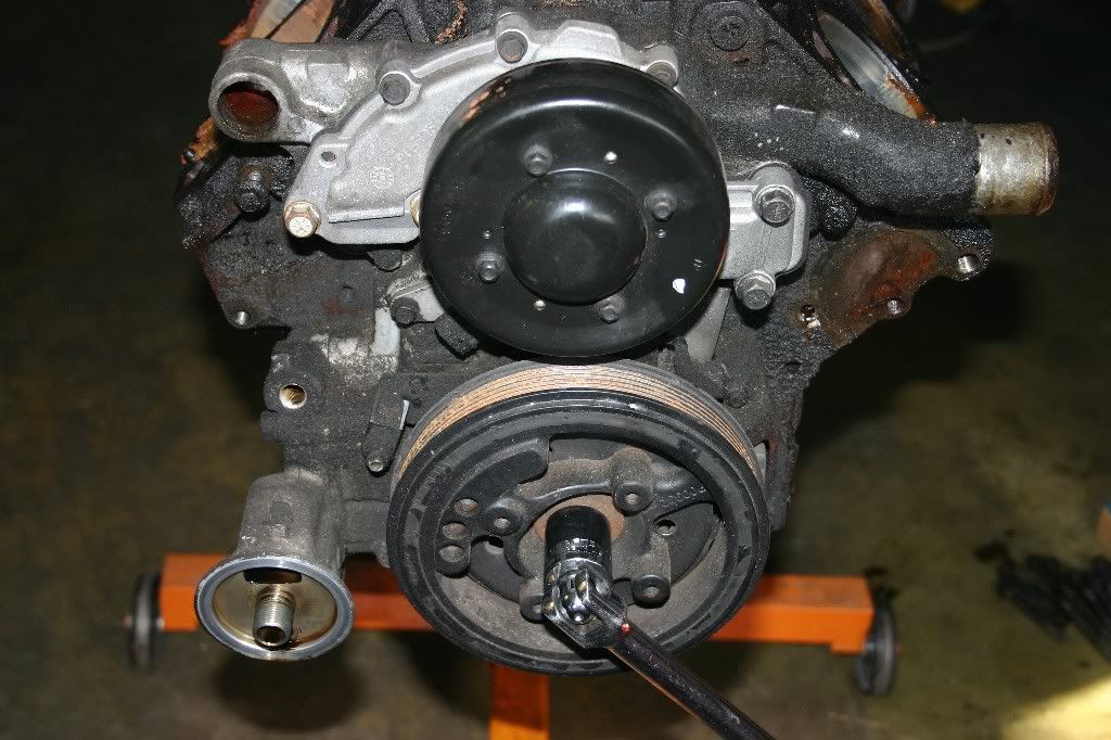
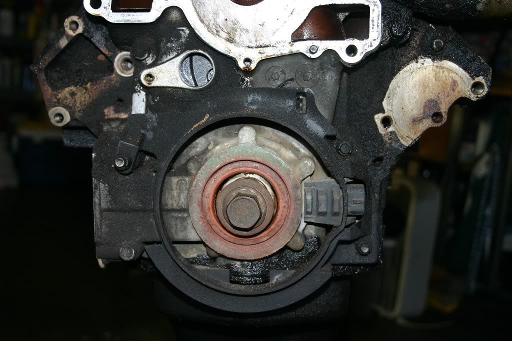
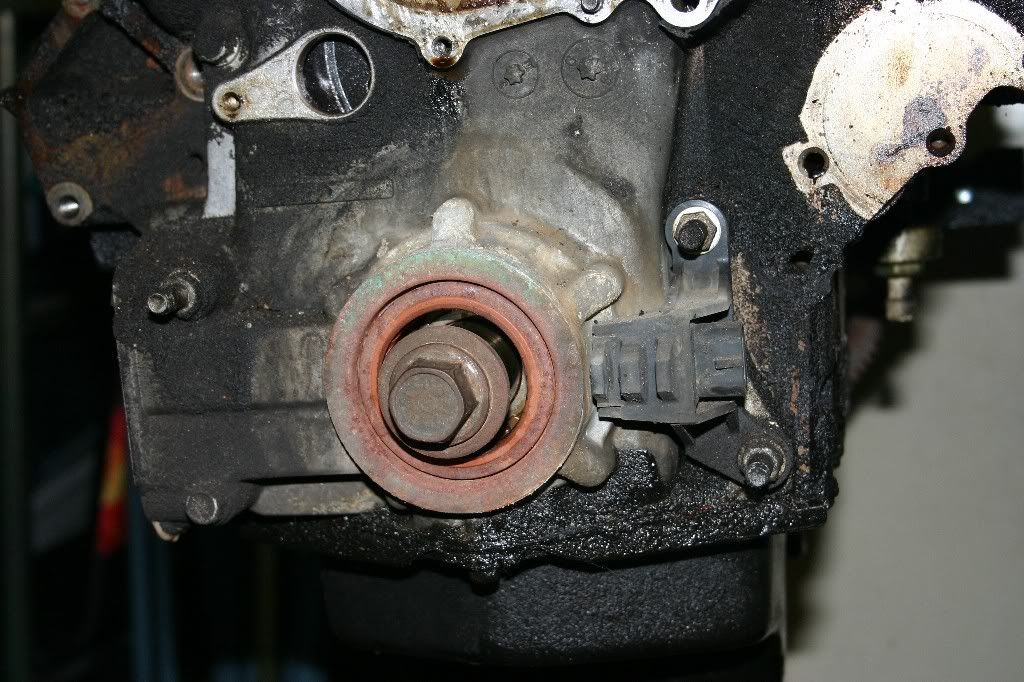
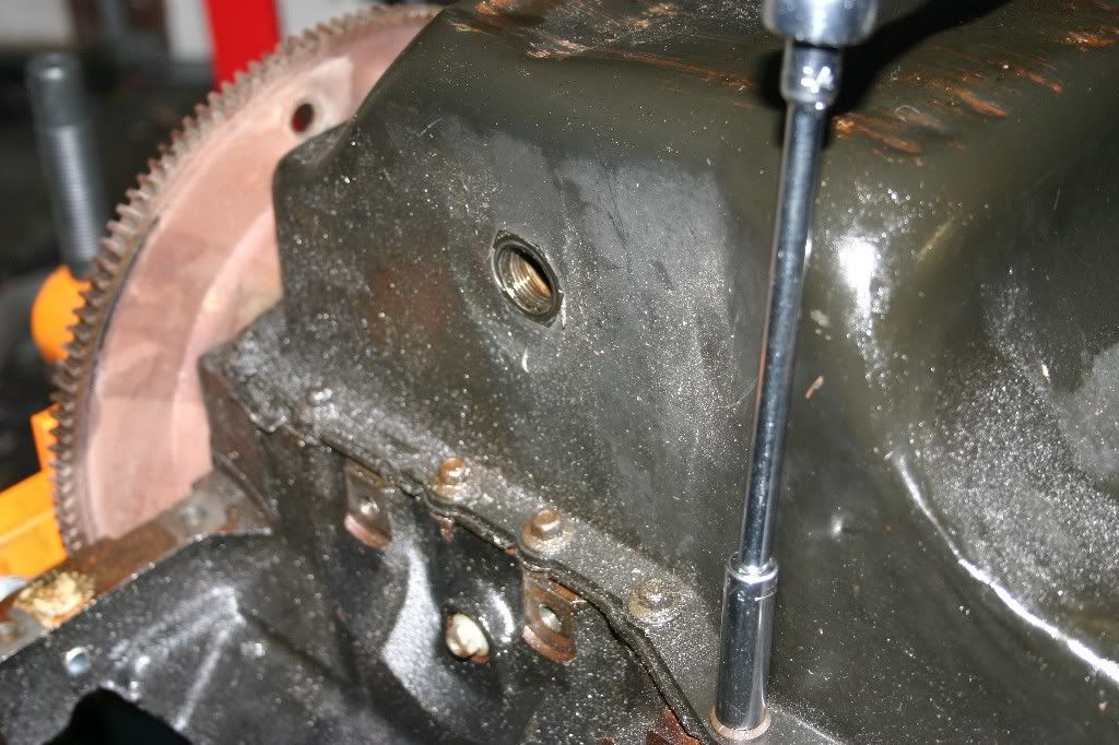
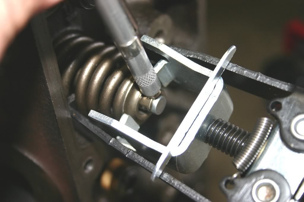
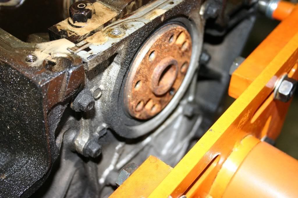
Before removing it, I want to take a measurement of the crank position sensor for future reference. With one photo, I have all me measurements for comparison purposes later.

Image


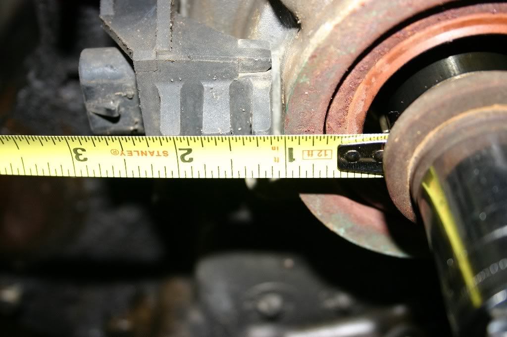
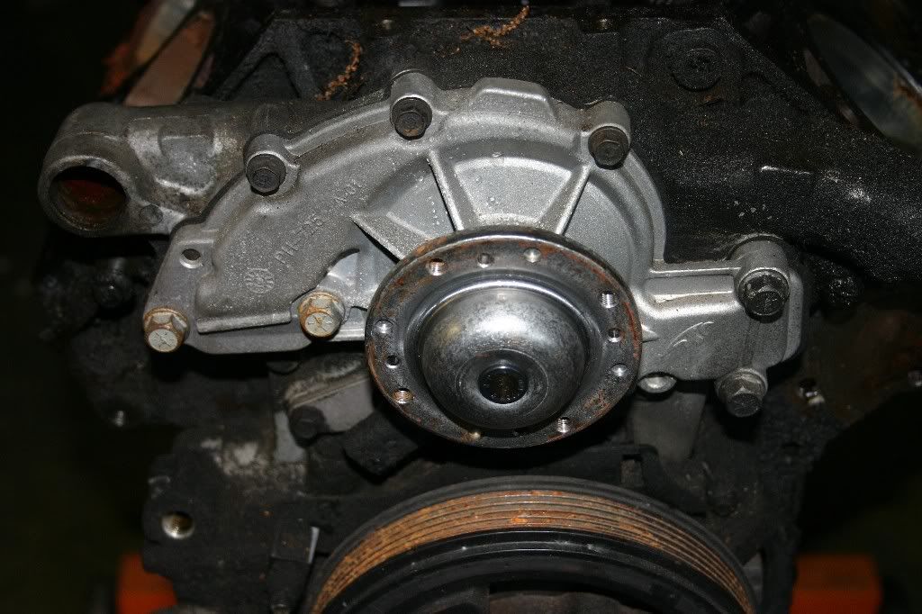
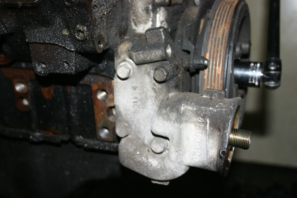
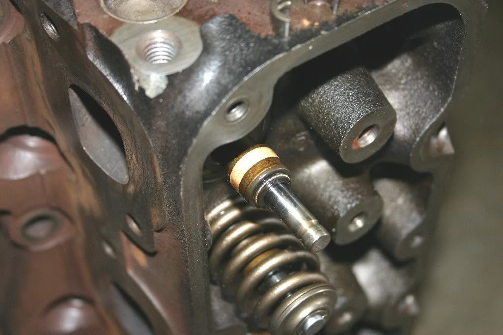
Now, for the timing cover and oil-pump assembly. Take off the crank position sensor and all of the exposed bolts (Six total)

Image


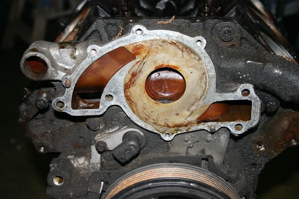
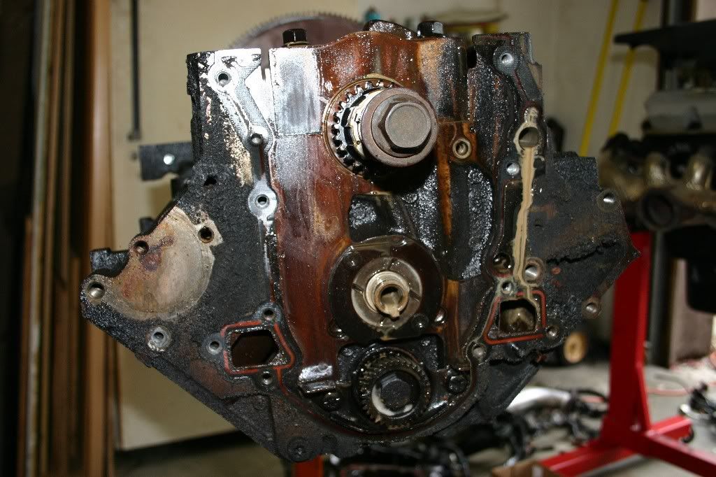
With a few taps of a rubber mallet, the timing cover and oil pup will come off the face of the block.

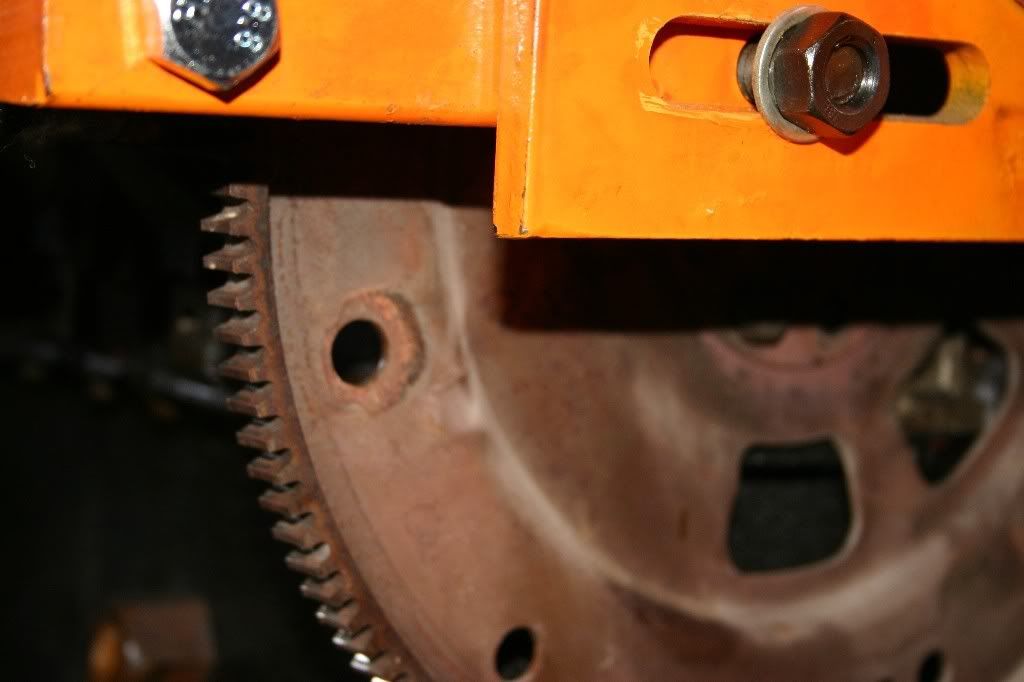
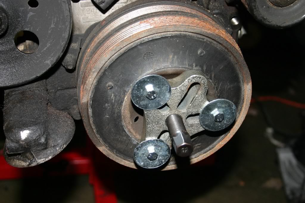
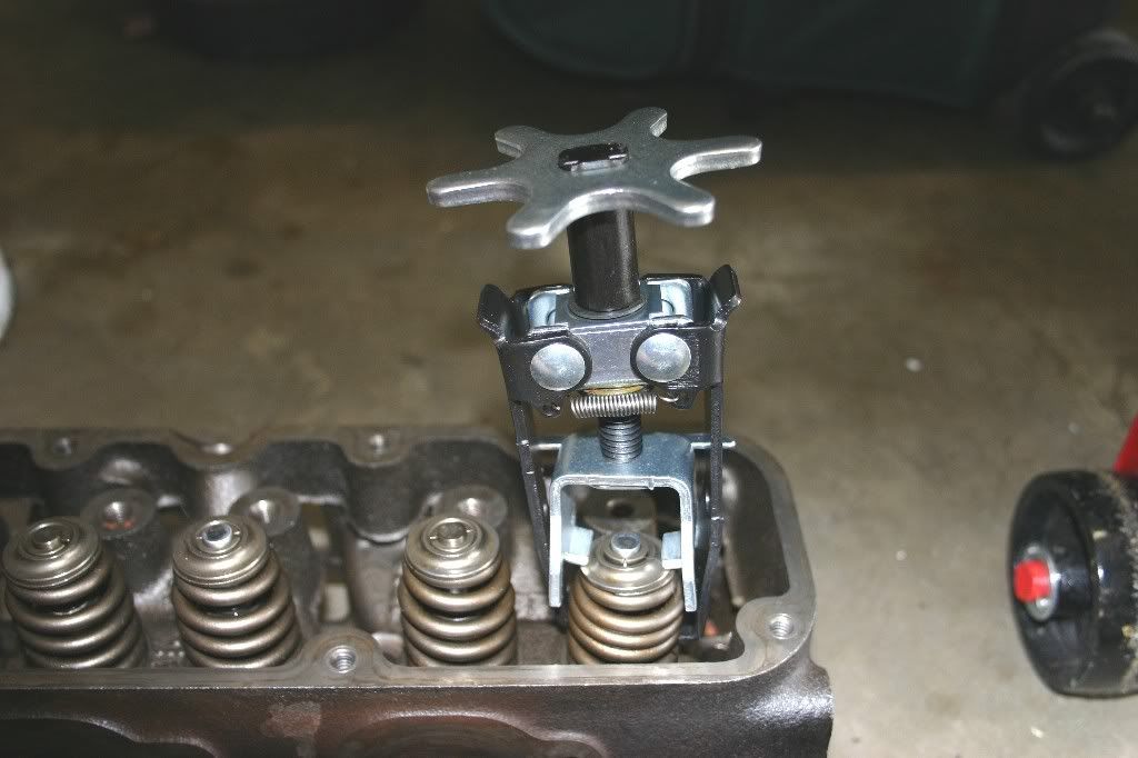
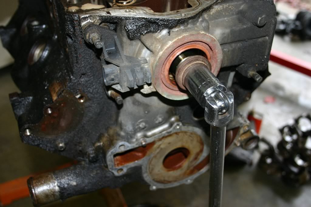
Now, we need to loosen the cam retainer bolts to remove the timing chain and tensioner. This is another really tight bolt, so just like removing the balancer bolt, I'm locking the crank in place using the flex plate at the other end.

Image


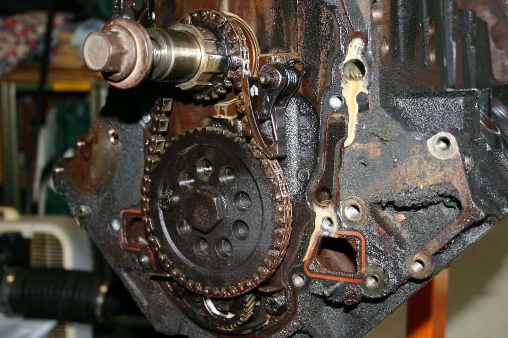
With the timing chain off, the oil-pump drive and other bits can come out. The tensioner is another discard item. The shoe of it wears down in contact with the timing chain and should be replaced if it has a visible track worn into it. The timing chain itself is a maybe item, it needs to be inspected and measured along with the drive gears to see if they warrant replacement. Note, I am not removing the camshaft at this time...it will be a lot easier to remove in a few minutes.

Image


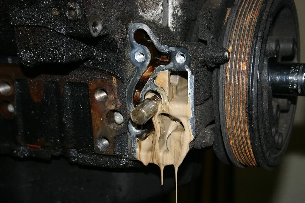
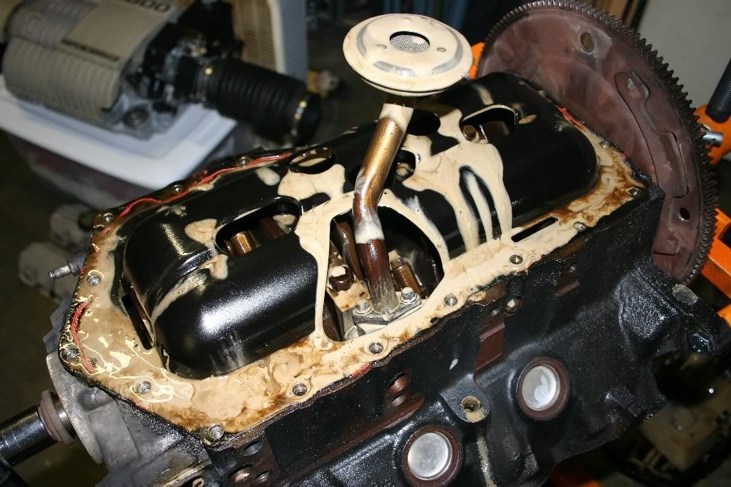
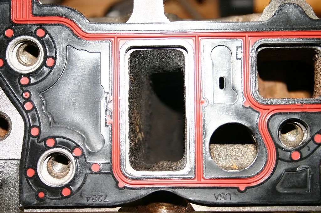
Ok, front cover is done, time to attack the rear cover. Remove the 10mm head bolts and pry the cover off (it's glued on with a paper gasket and some adhesive in addition to the bolts.)

Image


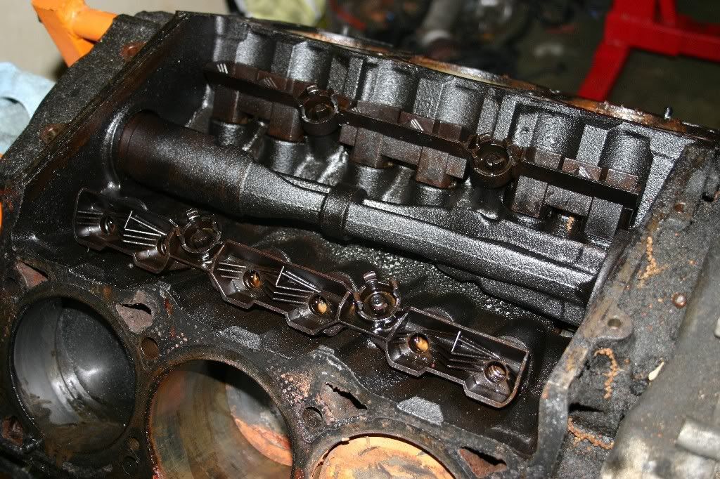
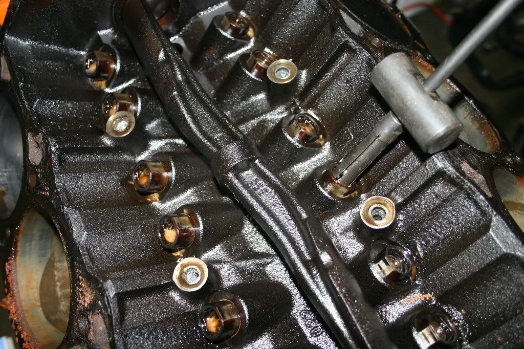
Now, with front and rear covers removed, time to remove the girdle bolts for the main caps. There are six of them in pockets machined in the oil pan rail. (three per side) with 10mm heads and they are all the same size.

Image


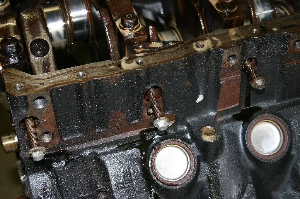
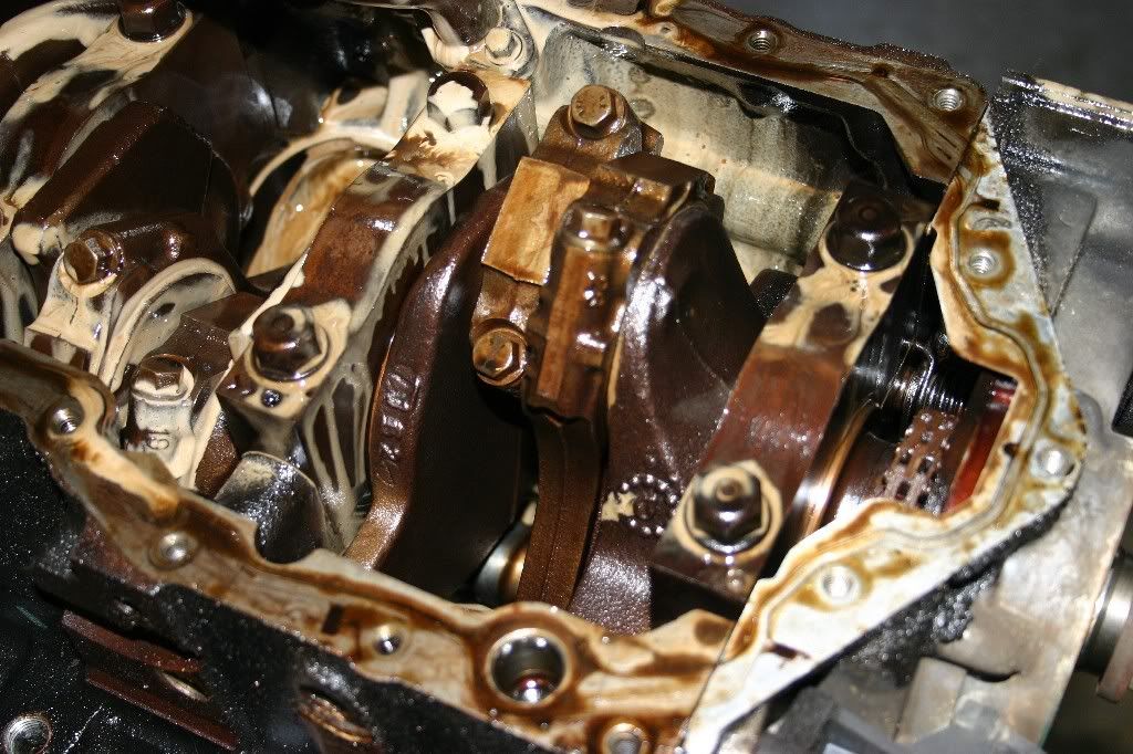
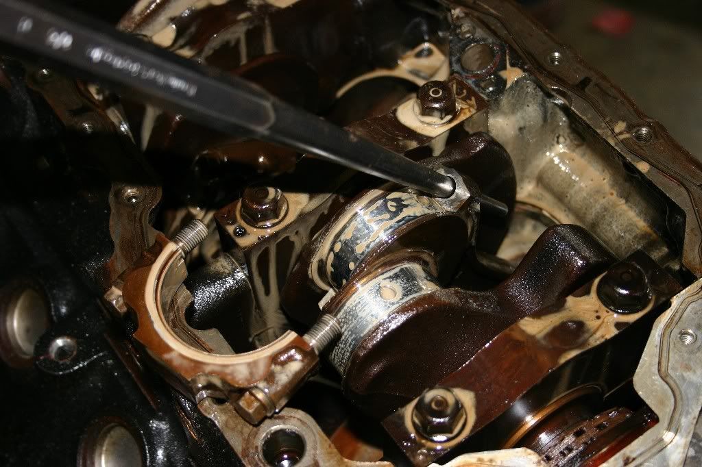
With the girdle bolts out, you can loosen the main journal bolts in preparation for removing the main caps. Word of caution, they are torqued pretty tight. Use a long breaker bar as well as position your hands to pull on the wrench while pushing on the block. If you are not careful, you can easily pull the whole motor and engine stand over and have it land on top of you. (not fun, it still weights about 100lbs at this point.)


Image


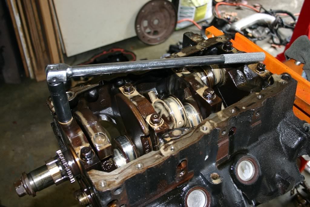
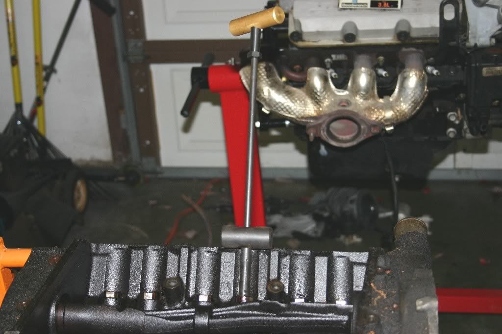
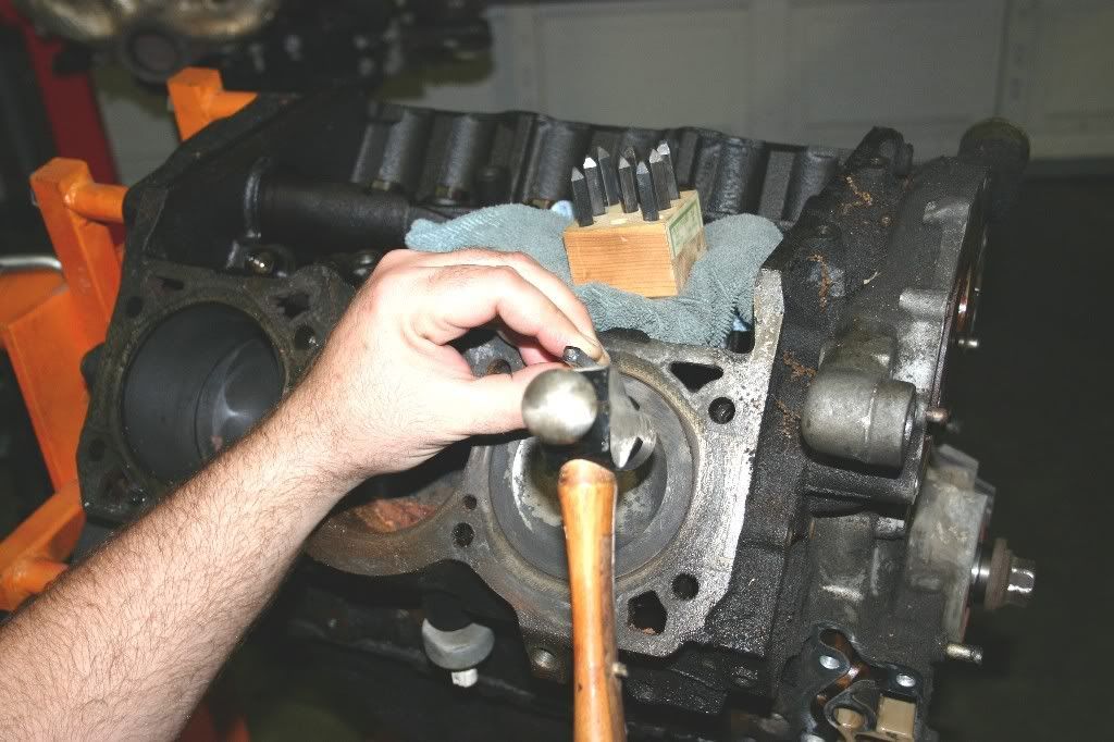
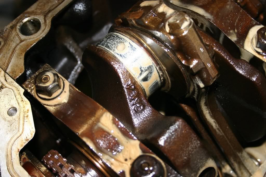
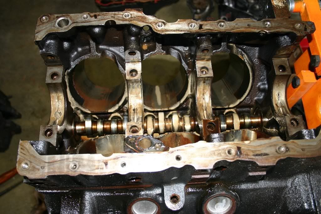
Now, Here's all the main caps loose and ready for the next step. There's a special tool for removing the main caps on the 3800 motor. It's a special jig that fits into the main cap bolt holes, grips them, and pushes on the oil pan rails to extract the caps out of the block. I don't have one, but a James pointed out, there's an alternative way. With the cap bolts loose, but still threaded into the block, turn the block right side up and tap on the crank with a block of wood and a mallet. Gravity will do the rest. Don't be in a hurry, tap a little on the crank nose, then the flex plate end, then slip the block into the cylinder bores and tap on the counter-weights inside the block. Resist the temptation of slipping a screwdriver into the gap between the block and caps, you’ll screw up the machined surfaces. When you have the caps most of the way out, turn the motor on the engine stand back to upside-down and finish removing the bolts, caps, bearing shells, and crank.


Image


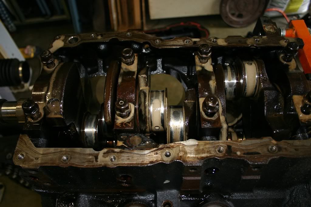
Crank is out. Looking at the underside of the motor, we can see the camshaft. Now is the time to remove it. Turn the motor back over and stick a hand up inside to support the part of the cam inside the block while pulling it out with the other hand. Don't be in a hurry, you have to work the cam lobes past three camshaft bearings. I know the cam bearings are trash, but if they were to be reused, the last thing you would want is a nice big scratch in them from a cam lobe.


Image


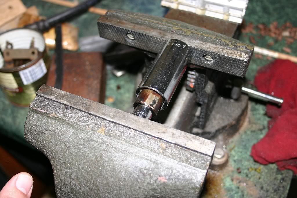
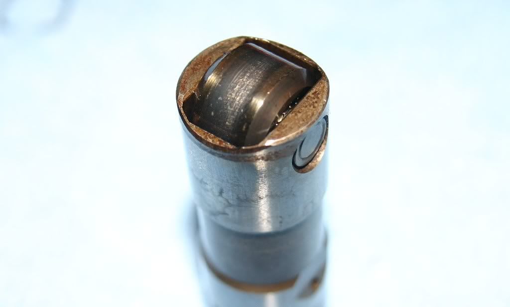
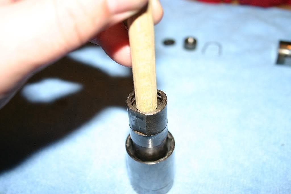
While I didn't photograph it, the balancer shaft comes out easily. Take out the two bolts and steel retainer on the timing cover end of the motor. Then, using a deep socket, drive the balancer out of the block from the bell-housing end towards the front of the motor. Couple of taps will unseat the ball bearings and their race out of the pocket in the front of the motor, then the balancer can be slid out of the block.

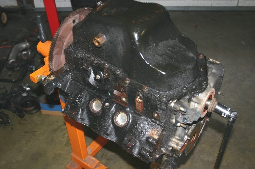
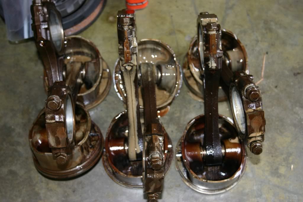
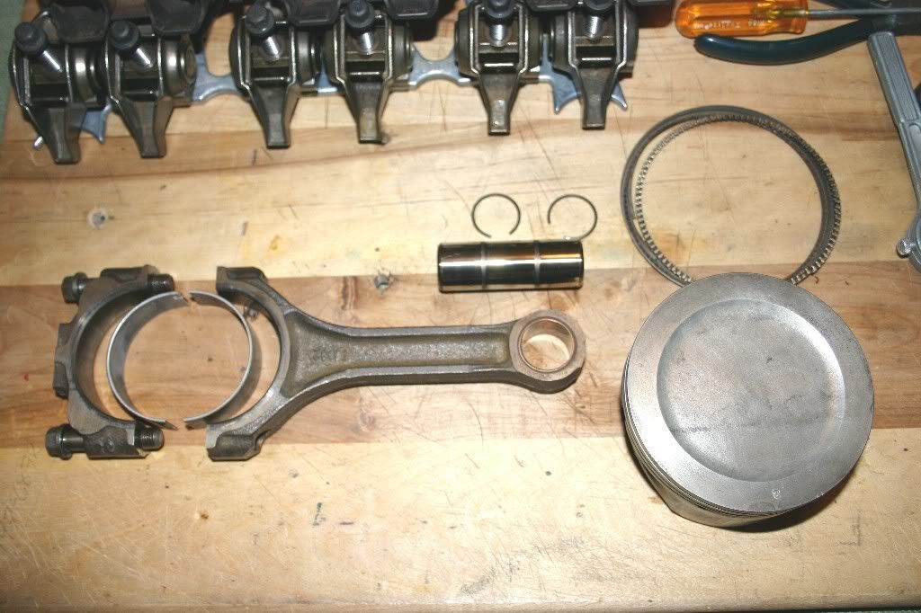
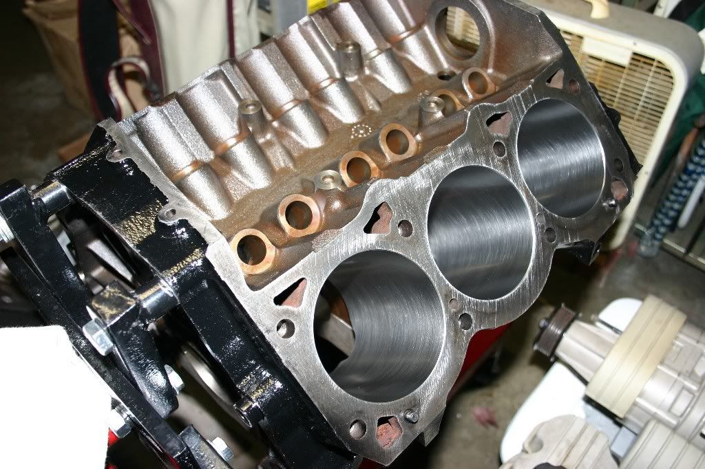
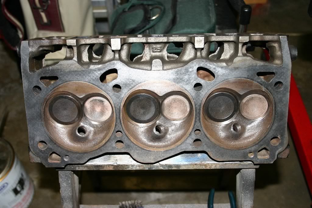
That brings us all the way down to a bare block and a big pile of parts.

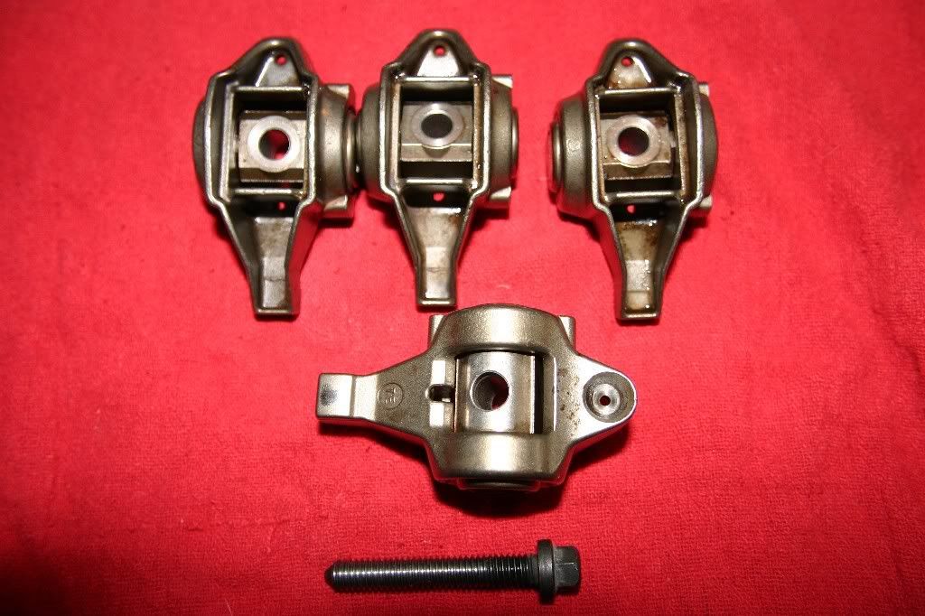
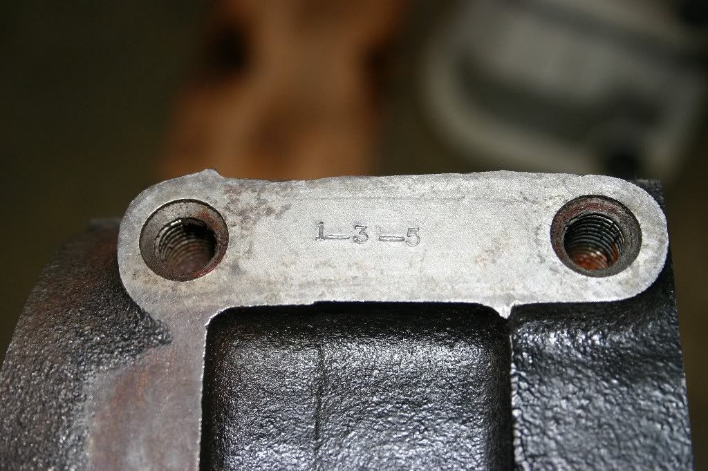
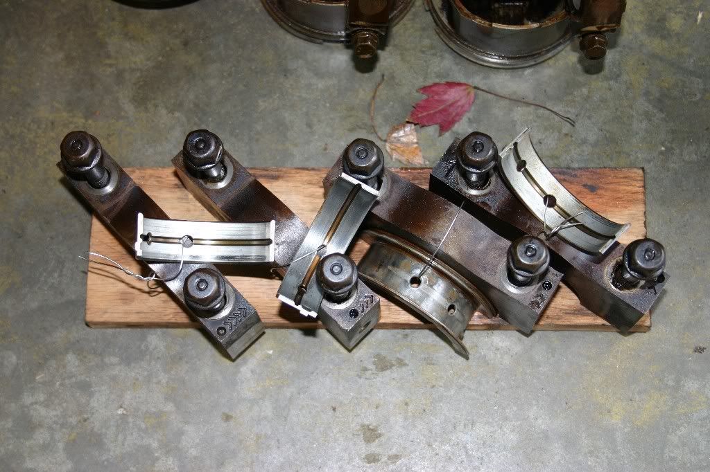
Here's the main caps and their bearings. They actually don't look too bad. A little material is impacted into the surface of a few of them, but otherwise they would be considered serviceable as-is. Note, I didn't stamp numbers into them like the rods. Normally you would do this, but GM did the work for you. Each cap is marked with the number of the journal it was fitted to, along with an arrow to indicate which way it goes in during reassembly.

Image


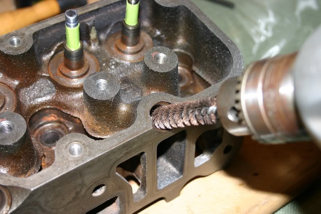
With all this done, the next phase is cleaning all the parts up. The block will need a lot of attention, so it is going straight to the machine shop to be hot-tanked and new cam bearings installed (The caustic cleaning process dissolves the bearings, so it is normal procedure to put new ones in and the shop will do it for me.)

That also brings up dealing with a machine shop.

1.) Never be in a hurry and Never put a time constraint on them. You don't want sloppy work and if you are clear that you are in no hurry, they will usually do a better job. You also get little freebies...like they might leave your block in the cleaning tank over the weekend for that really "squeaky-clean" block.

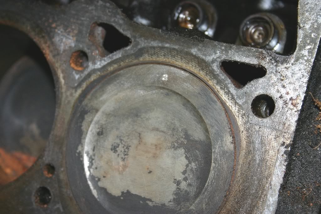
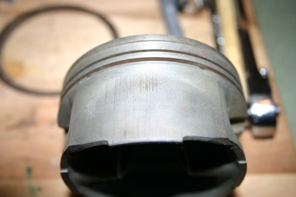
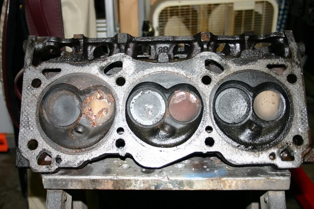
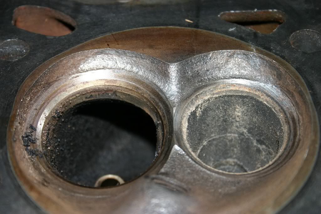
2.) Ask their advice and listen closely when they give it. Nothing pisses a machinist off more than being told their trade. I usually give them a general idea what I'm planning and ask them to check the block over to see if it is possible as well as hear their advice. On this block, I'm going to ask him to take a really good look at #2 cylinder. If it needs an overbore, it's going to get an overbore and the other cylinders will get one too.

3.) Bring cash. Yep, most prefer the currency of the realm and hate deadbeats as much as the rest of us.

_________________
Bye Bye 1990 Bonneville LE... Now it belongs to my daughter
In the Garage: 2009 Subaru Outback, 1987 Camaro, 2006 SV650S, 1995 Regal 182 "ASANAGI", 1962 Ford Galaxie 500, 1995 Ford F150 XL 4WD, 1953 Farmall Cub


Top
 Profile  
 
PostPosted: Sat May 24, 2008 11:30 am 
Offline
Retired Gearhead
Retired Gearhead
User avatar

Joined: Tue May 20, 2008 9:11 pm
Posts: 2156
Location: Fayette City,PA
Year and Trim: 1990 Bonneville LE
Originally Posted: Jan 03, 2007

Quote:
sandrock wrote: Will the shop knock-out and install new block plugs as well?


Around here, knocking out the freeze and oil gallery plugs are included in the fee for cleaning the block, so I'm not going to waste any time doing it. The place I'm taking the block to will also put the new ones in and stake them in place (there's a charge for the plugs, but it's not out of line.) Like the LT1 motor they did for me a few months ago, Jack will just hand me the oil galley plugs and I'll put them in myself. I'll let his boys put the water jacket plugs in for me.

Same goes for the cam bearings, since they can drive the new ones in properly. The cam bearings are in the main webs that go across the block at each main cap. To install them, start by putting the block up on it's bell housing flange. The tool to install the bearings is a long steel rod with a machined aluminum cap. Set a cam bearing in place, starting at the rearmost bearing, and use the tool to drive the cam bearing in place. The tool keeps the bearing square to it's pocket as it is driven in. You also have to line up the oil feed hole in the bearings to the oil passage in the block.

I didn't see the cleanout plug on the side of the block, but now that I know it's there, I'll go remove it. You find these on most motors. The internal passages are small and need to be machined at the factory with drills. As a result, a pipe plug(s) needs to go in to seal up the passage.

Looking at the main bearing shells, you can see there are two holes drilled in each along with a groove. One hole feeds oil into the crank journal. the other feeds oil back up to the cam bearings. In the crankshaft there are holes drilled at angles between the main journals and the crank journals. These feed oil from the mains out to the rod bearings. Any excess oil at this point will bleed out of the rod bearings and get slung around inside the block. A fair amount of it will also get shoved by centripetal acceleration up the connecting rod and end up lubricating the wrist pin and pooling in the underside of the piston crown. That oil will pass through the oil control rings in the piston and lubricate the cylinder bores.

The oiling system is pretty complicated, so yes, as James mentioned you need to clean the passages out. A rifle cleaning brush is going to be used extensively to clean out the passages.

While looking at the bearings, note that the #2 main cap bearing is different from the others. It has shoulders on it that wrap around the sides of the cap. This is the thrust bearing that keeps the crank from walking towards the front or rear of the block.

_________________
Bye Bye 1990 Bonneville LE... Now it belongs to my daughter
In the Garage: 2009 Subaru Outback, 1987 Camaro, 2006 SV650S, 1995 Regal 182 "ASANAGI", 1962 Ford Galaxie 500, 1995 Ford F150 XL 4WD, 1953 Farmall Cub


Top
 Profile  
 
PostPosted: Sat May 24, 2008 11:53 am 
Offline
Retired Gearhead
Retired Gearhead
User avatar

Joined: Tue May 20, 2008 9:11 pm
Posts: 2156
Location: Fayette City,PA
Year and Trim: 1990 Bonneville LE
Originally Posted: Jan 03, 2007

Ok, this evening's task was to take the block off the stand.

I put the bare block down on the bathroom scale and came up with 120lbs with main caps on.

Block is now safely tucked into the trunk of the '90 Bonneville for the 7:00am ride to the machine shop. (I really miss my old Astro Van ) Basic cleaning is $40 plus the freeze plugs and cam bearings. He's has also been asked to inspect the bores and see if an overbore is required.

All new parts purchasing is on hold pending the decision on an overbore.

If none is required and the pistons & rods check out, then the plan is to rebuild using the L36 rods and pistons and new rings.

If the motor needs an overbore +010, +020, or +030 to clear the cylinders, then the plan changes to purchasing new L32 pistons and the appropriate rods. Probably go with the Diamond pistons, but will call JE to see if they can make a forged piston for me.

Any overbore beyond +030 and the block is scrap. It could be over bored larger than +030, but my personal call will be to scrap the block and go get another one.

In the meantime, we'll pick up tomorrow with parts cleaning, starting with tearing down the roller-lifters.

_________________
Bye Bye 1990 Bonneville LE... Now it belongs to my daughter
In the Garage: 2009 Subaru Outback, 1987 Camaro, 2006 SV650S, 1995 Regal 182 "ASANAGI", 1962 Ford Galaxie 500, 1995 Ford F150 XL 4WD, 1953 Farmall Cub


Top
 Profile  
 
PostPosted: Sat May 24, 2008 11:59 am 
Offline
Retired Gearhead
Retired Gearhead
User avatar

Joined: Tue May 20, 2008 9:11 pm
Posts: 2156
Location: Fayette City,PA
Year and Trim: 1990 Bonneville LE
Originally Posted: Jan 06, 2007

Picking up where I left off...

The engine block is currently at Fastrac Machine Shop being boiled out. I should have word back on Monday as to whether it got an overbore. (In the conversation I left the overbore to Jack's discretion...if it needs one, he'll just go ahead an do it, if not, they will just hone the existing bores to remove any glazing and prep it to seal with new rings.)

With some free time on my hands, time to start cleaning up the lifters. And what a mess. The same spooge that was everywhere else in the motor was inside the lifters too, locking them in place (The spooge was too thick to pump through the lifter's orifices, so the lifters just locked up, just like a collapsed lifter.)

Here's an exploded view of the lifter. On the top row is a conventional Flat Tappet Hydraulic Lifter from a Small Block Chevy V8. On the bottom row is one of the Series II 3800 Roller Hydraulic Lifters. The parts from left to right: Lifter body, Return Spring, Piston, Reed Valve, Pushrod Seat, and Retaining Clip. On the right is just another assembled lifter.

Image

Here's a close-up of the lifter parts. If you have ever worked on motorcycle forks or taken a shock absorber apart then these parts should look rather familiar. The lifter works by sucking oil into the lower cavity, then metering a small amount into the upper cavity of the piston with every compression (cam lobe working to try to open the valve in the cylinder head.) The reed valve lets a little squirt of oil out through the pushrod seat where it pumps up through the hollow pushrod and lubricates the rocker arms and valves in the cylinder head. Without the oil in the lower cavity, the lifter is very spongy, but once the lifter "pumps up" full of oil, it becomes quite stiff and can transfer the force from the cam lobe to the rocker arm and valve. (This is why they are called "Hydraulic" lifters.)

Image


Normally, to take a lifter apart you just pick the retaining clip out of it's grove in the lifter body (keep your thumb over the end of the lifter to catch the parts and let off the spring tension.) These suckers were so gummed up that they needed to be manually pumped a few times just to get the parts out. Using a bench vise and a pair of appropriately size sockets, the lifter was gently, but firmly, squeezed repeatedly to force some of the gunk out of the cavities allowing someplace for solvent to get inside.

Image


Once the lifter is disassembled, the parts can be soaked in carb cleaner, kerosene, mineral spirits, or any other solvent to remove the cooked oil from the parts. DO NOT attempt to remove the roller from the lifter body. The pin is pressed in and the ends are deformed. If the roller is bad, or the roller bearings inside are bad, the entire lifter goes in the trashcan.

Here's the roller end of a roller lifter. What we are looking for is that the roller turns freely without any "clicking" (just like checking the wheel bearings on the car.) The surface of the roller needs to be free of any pits or burs. This one checks out and can be reassembled.

Image


Putting the lifter back together is pretty easy. A few drops of oil on the machined surfaces and the parts all slide back together. A wood dowel rod compresses the return spring and the retaining clip pops back in place.

Image


NOTE: When it comes time to actually reinstall these in the motor during assembly, I will be pre-oiling the lifters and manually pumping them up with oil before lashing the valves. This will be covered later. For now, the cleaned and reassembled lifters can be wiped down with oil and bagged to keep them clean till they are needed.

One down, eleven more to do....

Next stop, cleaning the rockers and pushrods.

_________________
Bye Bye 1990 Bonneville LE... Now it belongs to my daughter
In the Garage: 2009 Subaru Outback, 1987 Camaro, 2006 SV650S, 1995 Regal 182 "ASANAGI", 1962 Ford Galaxie 500, 1995 Ford F150 XL 4WD, 1953 Farmall Cub


Top
 Profile  
 
PostPosted: Sat May 24, 2008 12:05 pm 
Offline
Retired Gearhead
Retired Gearhead
User avatar

Joined: Tue May 20, 2008 9:11 pm
Posts: 2156
Location: Fayette City,PA
Year and Trim: 1990 Bonneville LE
Originally Posted: Jan 06, 2007

Quote:
2000SilverBullet wrote:
So besides the benefit of lower friction, the roller lifters can be reused on different cams. Are you saying they are good as long as the roller tip bearings are good?


Exactly, flat tappet lifters are disposable items. The surface of the lifter in contact with the cam wears into the cam and vice-versa. They can only be reused on the exact same cam, and on the exact same lobe on that cam. (If the lifter was on #6 Intake lobe, then it MUST be reinstalled on #6 Intake on that cam.) If a new cam is installed, then all the flat tappet lifters go in the trash. Most cam kits come with a set of new flat tappet lifters.

A roller lifter is reusable, in any location on the motor and on any cam (provided the cam is ground for roller lifters.)

The internal orifices and springs do not actually need to be checked beyond the holes being clean and the spring is intact. The spring's only function is to help return the piston to the top of the bore when the lifter hits the base circle of the cam lobe. There are no specs on how much tension it has or how big the holes are. Similarly, the retaining clip need only be check for it being seated, since it's only function is to keep the lifter assembled when it is out of the motor. When we set the valve lash, one of the things we are doing is compressing the lifter enough to ensure the pushrod seat doesn't hit the retainer when the motor is running.

There is a spec on the diameter of the lifter body in relation to the block's lifter bores. Until the block comes back, this will be an unknown number. (In other words, if the lifter bores are worn beyond the size this lifter fits, then an oversize lifter will need to be used, or the bore will need a sleeve to restore it to the proper diameter.) Too much slop between the lifters and the bores will result in low oil pressure and excessive wear over the motor's life.

Note the flash from the camera exaggerates the surface scratches in the polished surfaces of the lifter body. It looks severe in the photos, but is really quite minor.


More amusing facts: The Series II 3800 uses the exact same lifter as the small block Chevy (LT1 and post 86 with roller cam, etc.) So, if your vendor doesn't list the 3800 in the charts, you can order lifters for the V8 and be good to go.

I haven't checked the lifter bore spacing on the block yet, but it is quite likely it is the same as the V8 as well (Meaning all the aftermarket Lock-Bar style roller lifters work too.)

Did a little comparative shopping. A replacement set of roller lifters (oem style locks) run about $150.00 at the low end, to about $250 for brand name Hi-Performance parts. By comparison, a set of Flat Tappet lifters runs about $40 for the low end. You can pretty much see the reasoning for reusing roller lifters whenever possible.

Another tidbit: You CAN use regular flat tappet lifters in this motor if you NEED to. For example, let say you want to run a camshaft that has a grind not available in a roller lifter. You can still run it if it fits in the block. You must however use flat tappet lifters and longer pushrods to do it. Flat tappet cams have their lobes ground at a very shallow angle. Flat tappet lifters have a very slight dome in the face of the lifter. The two work together to spin the lifter in the bore and even out the wear on the lifter. If you stuck a Roller lifter on that same cam, you would screw up the roller because of the side-load the angled cam lobe would put on the flat roller.

_________________
Bye Bye 1990 Bonneville LE... Now it belongs to my daughter
In the Garage: 2009 Subaru Outback, 1987 Camaro, 2006 SV650S, 1995 Regal 182 "ASANAGI", 1962 Ford Galaxie 500, 1995 Ford F150 XL 4WD, 1953 Farmall Cub


Top
 Profile  
 
PostPosted: Sat May 24, 2008 12:17 pm 
Offline
Retired Gearhead
Retired Gearhead
User avatar

Joined: Tue May 20, 2008 9:11 pm
Posts: 2156
Location: Fayette City,PA
Year and Trim: 1990 Bonneville LE
Originally Posted: Jan 06, 2007

Well, I didn't think I would get this far without finding something that needed replaced, but here's our first candidate for the trashcan.

I cleaned out the pushrods by soaking them in solvent, then blew out the inside of the tubes with compressed air.

I Inspected the ends of the rods for wear and most of them came up looking like this:

Image

Take a good look at the one on the left vs. the one on the right. Notice how the ball on the left is worn and misshapen. This is the rocker end of the pushrod and a sign that the valve train wasn't getting enough oil. With all the goop inside the lifter bodies, this shouldn't have come as a surprise.

One rod will be kept as a reference for length, the rest get pitched in the trash.

If the rods ends had passed this inspection, the only other test would have been to roll them on a plate of glass to see if any were bent. (A good one will roll, a bent one would not roll.)

Follow Up Note: I'm going to use Crane One-Piece pushrods, pn 95621-16 which dimensionally match up with our existing rods. ( 7.050" long, 5/16th" diameter, heat treated for use with guide plates.) Another alternative is Crane 11628-16..same dimensions in a conventional ball and tube style pushrod.

Next stop is the rockers.

Cleaning the rocker arms is much like cleaning everything else. Soak them in solvent, take them out and wipe them down. Check the trunion, it should swivel freely on it's bearings. Check the tip and the pocket the pushrod sits in for wear. After seeing the pushrods, I was expecting the worst, but the rockers look to be in good shape overall.

Image

<Edit Note - comment about cleaning the rocker bolts removed: Rocker Bolts on this motor are of the Torque To Yield type and are replaced with new ones on overhaul. In the original article I mistakenly thought the bolts were common and reusable. After comments from Willwren and others, the bolts were determined to be TTY fasteners and discarded for new.>

This valve train setup is a little different from the usual stud & guide plate setup I'm used to. It also really limits what you can do for aftermarket rockers if you want to change to a higher ratio. You probably can convert the heads to run studs by drilling the bosses out, spot facing them down to a suitable height, and threading them for conventional studs. I'm not planning of making that kind of change, so I'm leaving the valve train in its stock form.

_________________
Bye Bye 1990 Bonneville LE... Now it belongs to my daughter
In the Garage: 2009 Subaru Outback, 1987 Camaro, 2006 SV650S, 1995 Regal 182 "ASANAGI", 1962 Ford Galaxie 500, 1995 Ford F150 XL 4WD, 1953 Farmall Cub


Top
 Profile  
 
PostPosted: Sat May 24, 2008 12:25 pm 
Offline
Retired Gearhead
Retired Gearhead
User avatar

Joined: Tue May 20, 2008 9:11 pm
Posts: 2156
Location: Fayette City,PA
Year and Trim: 1990 Bonneville LE
Originally Posted: Jan 08, 2007

So far the list of replacement parts includes:

1.) Main Journal Bearings
2.) Rod Bearings
3.) Cam Bearings (Included in the block prep charge from machine shop)
4.) Balancer Shaft bushing (also included with block)
5.) Pushrods
6.) Head Bolt set
7.) Rocker arm bolt set
8.) all gaskets and seals
9.) Plastic Lifter retainer/locking plates (2)
10.) Cam Chain Tensioner

That should be about $350 to $400 worth of bits. Not bad thus far, could be worse.

Today I should find out about the block's condition to see if new pistons will be required.

_________________
Bye Bye 1990 Bonneville LE... Now it belongs to my daughter
In the Garage: 2009 Subaru Outback, 1987 Camaro, 2006 SV650S, 1995 Regal 182 "ASANAGI", 1962 Ford Galaxie 500, 1995 Ford F150 XL 4WD, 1953 Farmall Cub


Top
 Profile  
 
PostPosted: Sat May 24, 2008 12:31 pm 
Offline
Retired Gearhead
Retired Gearhead
User avatar

Joined: Tue May 20, 2008 9:11 pm
Posts: 2156
Location: Fayette City,PA
Year and Trim: 1990 Bonneville LE
Originally Posted: Jan 08, 2007

Phone rings, the heavens open, and a word is spoken from on high....."Overbore"

Ok, that's the word from Jack Yeager at the machine shop. To get the block cylinders squeaky clean, straight, and true, they bored the block 0.030" over. I can pick the block up tomorrow afternoon.

Time to add about $400+ to the budget on the next payday. I'm going to use blower pistons and matching rods. I need to double check that overbore number. I may have to have the pistons custom made.

Any suggestions on a target compression ratio to aim for? I'm tempted to go with the higher N/A compression ratio with the blower heads...but the lower stock ratio would probably work better on mid-grade pump gas.

Quote:
Reply to above from willwren:
Try to target midway between the 9.4:1 L36 and the 8.5:1 L67. You SHOULD be able to benefit from the higher static compression ratio that way, and MIGHT still be able to run a stock 3.8 pulley with no KR.

Something to think about.

There are distinct benefits to raising the static compression ratio, but you don't want to raise it to the point that you can't run an easily obtained 3.8 pulley.


also

Quote:
Reply from 2000SilverBullet:
That would be a good target, 9.0 : 1
If you port and polish it will help.

Go the extra step and have the entire rotating mass balanced. You have to anyway.

_________________
Bye Bye 1990 Bonneville LE... Now it belongs to my daughter
In the Garage: 2009 Subaru Outback, 1987 Camaro, 2006 SV650S, 1995 Regal 182 "ASANAGI", 1962 Ford Galaxie 500, 1995 Ford F150 XL 4WD, 1953 Farmall Cub


Top
 Profile  
 
PostPosted: Sat May 24, 2008 12:38 pm 
Offline
Retired Gearhead
Retired Gearhead
User avatar

Joined: Tue May 20, 2008 9:11 pm
Posts: 2156
Location: Fayette City,PA
Year and Trim: 1990 Bonneville LE
Originally Posted: Jan 09, 2007

Picking up where I left off. The only part of the rocker assembly left are the plates that serve as the base of the rockers on the heads. Again, clean them with solvent and check the die cast part over for damage. Since they are going to be torqued in place by the rocker arm bolts, look for burs and cracks in the area around the bolt holes. Discard if damaged.

Image


Now that we launched off into the piston area. Here's our old friend #2 piston completely disassembled: Parts from left to right: Rod cap bolts, rod cap, rod bearings, rod, above it is the wrist pin and wire retaining clips, the piston itself, and above the piston the stack of compression and oil control rings.

Image

To take one apart, soak it in solvent. Remove the two wire retaining clips on the wrist pin, push the wristpin out (a deep socket and a rubber mallet help it out if it is really tight ) then remove the rings from the piston. They are thin and flexible, so you can use a fingernail to get them out or a pair of piston ring pliers. You'll need the pliers to put new ones on, so it's a tool to obtain at some point. Just be careful not to damage the ring grooves while doing this. You can also snap a ring in half and use the sharp end of the trashed ring as a scraper to clean carbon out of the piston ring groove.

Checking wear on the pistons means looking at the skirts on both sides of the piston:

Image
Image


These look pretty normal and would be reusable if it were not for the overbore of the cylinder. Note the half-circle haze on the skirt. That is the wear caused by the piston tipping in the bore while going up and down. These are normal and you can still see the original machining marks on the piston.

Moving on to the wristpin end of the rod. There is a bronze bushing in the rod that the wristpin rides on. Check it for inside diameter and wear. If it is too loose a fit to the wristpin, then it can be replaced, though it is more common to replace the entire rod.

Image


Last we are looking at the crank journal end of the rod. With the bearings out, check the diameter and for any nicks and burs in the machined surface. At this point, you can check the rods for being flat and the two bores being parallel. You can also weigh the rod against the others to see how they stack up as a set.

Image


These rods are not going to be reused, as I will be substituting new L67 rods during reassembly to go with the new pistons.

_________________
Bye Bye 1990 Bonneville LE... Now it belongs to my daughter
In the Garage: 2009 Subaru Outback, 1987 Camaro, 2006 SV650S, 1995 Regal 182 "ASANAGI", 1962 Ford Galaxie 500, 1995 Ford F150 XL 4WD, 1953 Farmall Cub


Top
 Profile  
 
PostPosted: Sat May 24, 2008 12:45 pm 
Offline
Retired Gearhead
Retired Gearhead
User avatar

Joined: Tue May 20, 2008 9:11 pm
Posts: 2156
Location: Fayette City,PA
Year and Trim: 1990 Bonneville LE
Originally Posted: Jan 13, 2007

First of the L67 rods showed up, time for a little comparison:

On the top is the L36 rod from the motor, on the bottom is the L67 rod. Construction is similar, using a bronze bushing on the wristpin end. The L67 rod is shorter and heavier in section and mass.

Image

L36 Rod: 633g (rod, cap, and bolts only..no bearings)
L67 Rod: 688g (rod, cap, and bolts only..no bearings)

Here's an L67 piston that came on the rod: Note the teflon coating on the piston skirts as well as the coating on the crown.

Image

L36 Piston w/wristpin: 497g
L67 Piston w/wristpin: 554g

And last, here's the replacement pistons I am going to use: Federal-Mogul Sealed Power PN H871CPA 0.030 overbore.


Image


Replacement L67 Piston w/wristpin: 560g

Hope this makes it pretty clear why the crank will need rebalanced after doing this substitution. The change in mass is going to be 118g per piston/rod assy, or a total change of approx 708g for the entire motor. That's like adding and entire extra piston to the motor's rotating mass.

Here's a little factoid for you: The factory GM L67 piston was actually cast by Alcoa Aluminum. Inside the skirt, opposite the casting number 23523E is the stylized "AE" casting mark that Alcoa uses. The L36 piston was also cast by Alcoa. A forged product made by Alcoa would have the same markings, except for a stylizes "AF" mark.

Ok, cocktail party conversation aside, the reason for going with Federal-Mogul cast pistons over aftermarket forged race pistons is pretty simple. $$$$$ and actual need. The quotes I got for custom pistons in a 0.030" overbore were hovering around $800.00 for the set, with a long delay before they were made. The Federal-Mogul pistons were $275.00 and on the shelf. Spending an extra $500.00 on a motor that would probably spend it's life bagged on an engine stand didn't make any sense. This motor is just a spare should the other factory assembled L67 die and need an overhaul.

_________________
Bye Bye 1990 Bonneville LE... Now it belongs to my daughter
In the Garage: 2009 Subaru Outback, 1987 Camaro, 2006 SV650S, 1995 Regal 182 "ASANAGI", 1962 Ford Galaxie 500, 1995 Ford F150 XL 4WD, 1953 Farmall Cub


Top
 Profile  
 
PostPosted: Sat May 24, 2008 12:55 pm 
Offline
Retired Gearhead
Retired Gearhead
User avatar

Joined: Tue May 20, 2008 9:11 pm
Posts: 2156
Location: Fayette City,PA
Year and Trim: 1990 Bonneville LE
Originally Posted: Jan 13, 2007

Since we are still in parts cleaning mode, it's a little premature to be doing anything with the block. However, it came home from the machine shop and is resting comfortably on the engine stand.

Image

Moving right along, there's a lot more to do, so I'll pick up the narrative with the cylinder heads.

Ed Morad (Morad Parts Company) shipped me a pair of L67 heads for use on this motor. So far, I've scraped all the gasket surfaces and cleaned out the carbon in the combustion chamber in preparation for disassembly. Here's the pictures of the heads along each gasket surface. The combustion chamber is the fast-burn cardioid chamber found in a lot of late-model heads.

Image
Image
Image


Now, for comparison, here is one of the original L36 cylinder heads.


Image
Image


Some things to note:

An L36 head is no better or worse than an L67 head when it comes to airflow. It cannot be, since the two are based on the exact same cylinder head casting and use the same chamber volume, runner dimensions, intake and exhaust valves, etc.

If you take a look at the valve cover and intake manifold flanges, you'll see the only physical difference in the heads. The three machined injector pockets. Note, the L36 has everything needed for a machinist to add the pockets, so with a little shop time on a milling machine, your L36 heads can become L67 heads with very little effort. I may end up doing this to these L36 heads, just to have them as spare parts for later use.

Next step, removing the valves for cleaning, checking guides, and replacement of the valve stem seals. I'll also lap the valves into the seats prior to assembly, so the heads will have a good seal...about as good as new as you can get.

_________________
Bye Bye 1990 Bonneville LE... Now it belongs to my daughter
In the Garage: 2009 Subaru Outback, 1987 Camaro, 2006 SV650S, 1995 Regal 182 "ASANAGI", 1962 Ford Galaxie 500, 1995 Ford F150 XL 4WD, 1953 Farmall Cub


Top
 Profile  
 
PostPosted: Sat May 24, 2008 1:15 pm 
Offline
Retired Gearhead
Retired Gearhead
User avatar

Joined: Tue May 20, 2008 9:11 pm
Posts: 2156
Location: Fayette City,PA
Year and Trim: 1990 Bonneville LE
Originally Posted: Jan 13, 2007

Taking down the cylinder heads...

First, I arbitrarily decided which head will go on which cylinder bank, then stamped the numbers into the accessory flange on the outside of the head. Here's the "1-3-5" bank head.

Image

Next, fit a valve spring compressor over the spring and tighten it up.

Image


With the spring compressed, the two retaining locks can be removed. (using a small magnet to pick them up out of the slots) If you can't get to them, the valve is probably glued to the retainers with cooked oil. A little tap on the face of the valve with a rubber mallet will pop them out.

Image

Retainer and spring is out, revealing the valve stem seal underneath. At this point, pull the valve out of from the chamber side and remove the valve stem seal with a pair of pliers.


Image

Ok, both valves out and soaking in solvent to clean them off. Here's the combustion chamber. You can see the stock 3-angle valve job on the valve seats. These look pretty good, no pitting in the seats at all. Once the valves are clean, they will be re-lapped into the seats and the whole head reassembled.

Image

_________________
Bye Bye 1990 Bonneville LE... Now it belongs to my daughter
In the Garage: 2009 Subaru Outback, 1987 Camaro, 2006 SV650S, 1995 Regal 182 "ASANAGI", 1962 Ford Galaxie 500, 1995 Ford F150 XL 4WD, 1953 Farmall Cub


Top
 Profile  
 
PostPosted: Sat May 24, 2008 1:20 pm 
Offline
Retired Gearhead
Retired Gearhead
User avatar

Joined: Tue May 20, 2008 9:11 pm
Posts: 2156
Location: Fayette City,PA
Year and Trim: 1990 Bonneville LE
Originally Posted: Jan 14, 2007

Ok, with the heads taken down and cleaned of carbon (or at least as much as I could scrape and wash out) time to start the inspection process.

First, the head needs to be checked for warpage. You need a good machinist’s ruler/straight edge to do this (one of the I-beam types) Lay it across the machined surfaces and use feeler gauges to measure any gaps. The critical one is the head-to-block deck surface, since this will provide the clamping force on the head gasket to seal it up. These check out pretty well, so we'll keep on trucking on the rebuild.

If the head is warped, you have two choices:

1.) Rebuilt or New replacement heads. Considering the price of the heads, this is a viable option. Same will hold true if any of the valves or guides are screwed up...it's the law of diminishing returns in action. The cost to fix the head can soon exceed the cost to replace them. (There are a few motors in the world that are so rare as to warrant doing a lot of work to refurbish the original parts, since the replacements are made of pure "Unobtainium"...the Series II 3800 is not one of them.)

2.) Resurface the existing heads to square them back up. Note: This has some negative effects as well. Removal of material from the head means the chamber volume of the heads is reduced, also, the intake manifold may also need surfaced too. The heads will sit a little lower and move the intake manifold flanges down closer to the block deck.

Another important little tidbit involves the block deck surface. The machine shop checked that for me and did not have to resurface the deck. That's good news to me, the 3800 is NOT a "zero-deck" motor (as we'll see when we reassemble the block) The pistons extend beyond the block deck into the head gasket area. Any change to the block's deck would mean either shim head gaskets or machining the pistons down so they don't hit the head.

But we were talking about cylinder heads, so here are a pair of cleaned up valves:

Image

The top valve is the #1 exhaust valve, the bottom one is #1 intake. Note the long silver "scratches" down the stems...they aren't scratches at all, just the reflection of the camera flash on the hard-chrome finish of the valve stem. Each valve is made of two parts. The stem is hard-chromed steel to give it long wear in the guides. The "Valve" is a milder cast steel that has been brazed to the end of the stem. It's done this way so the mating surface of the valve to the seat can be ground to a good seal.

Cleaning the valves is pretty simple. Soak them in solvent, then scrub the carbon off. When they are clean, check the diameter of the valve stem with a micrometer. You are looking for any taper in the stem that would be an indication of wear and allow the valve to rattle against the valve seat. Also, if the motor was starved of oil, you would see a lot of wear down here.

Last, check the width of the seat area on the valve. If it gets too wide, then the valve needs to be replaced, also if any ridged have formed on either the lip of the valve or it's seat in the head, both will need to be re-machined or replaced.

With the valves cleaned up, the valve guides in the cylinder head need to be cleaned out. A 30caliber rifle bore brush (phosphor bronze, not steel) is the perfect fit to scrub out the guides. You can check the diameter of the guides with a set of pin gauges, however I found this to usually be a waste of time. If you didn't find any damage on the valve stems, then it's highly unlikely there is any problem with the guides. If you do have a problem with a valve stem, then the only solutions are to ream the guide larger and use an oversize valve..or ream the guide WAY oversize and install a sleeve to restore the original bore diameter to the guide.

Lapping valves....

With the valves ready for reassembly, the seats need to be lapped using the actual valve that will ride on it. Lapping compound is like liquid sandpaper. It has a fine grit (around 600) and a little smear of it around the lip of the valve is all it takes. Apply a little pressure to the valve to force it against the seat and spin it in the bore. That will polish both the valve and seat together, giving you a nice tight seal when the valve is closed. Clean it off with solvent when you are done.

Here's #1 cylinder valves ready to be lapped into the seats:

Image

_________________
Bye Bye 1990 Bonneville LE... Now it belongs to my daughter
In the Garage: 2009 Subaru Outback, 1987 Camaro, 2006 SV650S, 1995 Regal 182 "ASANAGI", 1962 Ford Galaxie 500, 1995 Ford F150 XL 4WD, 1953 Farmall Cub


Top
 Profile  
 
PostPosted: Sat May 24, 2008 1:24 pm 
Offline
Retired Gearhead
Retired Gearhead
User avatar

Joined: Tue May 20, 2008 9:11 pm
Posts: 2156
Location: Fayette City,PA
Year and Trim: 1990 Bonneville LE
Originally Posted: Jan 14, 2007


Here's a better view of lapping in action:

Image


See the dull grey ring on the exhaust valve, that's the surface created by the lapping compound. It should be uniform in width, and not missing any spots. This is a visual sign of where the valve surface is in contact with the valve seat. For the factory 3-angle valve job, that's about the right width. For a competition 5-Angle or 7-Angle valve job, the contact area is much thinner. The radius of the both the valve and seat is smoother, so they get a little better airflow.

Down side to a multi-angle valve job is that they don't last as long as the 3-angle factory valve job. Yes, they flow better, but the seat surface is thinner. Since many racers run heavier than stock valve springs, the force applied to the smaller valve seat surface is higher. You'll see "peening" or dents in the valve seat surface forming sooner.

High-end valve tricks like "Swirl Polishing", more angles, etc. do work, for a while, on race motors. If you are looking for max performance, I recommend doing it and living with the higher cost over the life of the motor. But on a street motor, carbon build-up on the valves and seats will render these tricks useless in a few hundred to a thousand miles. I guarantee that is you pull the heads of a street motor after a few thousand miles of use, they will look just as nasty as these did when I started cleaning them. Running without EGR, and a good fuel-air mixture will keep them cleaner and make the tricks work longer, but in the end, the valve job will wear out and have to be redone.

Hence, I'm going to stick with the factory valve job. It's not as efficient, but will last longer in the application this motor is going to be used in.

When each valve is done, a little wrap of masking tape on the valve stem on top will keep the valves in place and protect the seats until we're ready to finish assembling the heads.

With the valves lapped back in, we still have some more finishing work to do on the cylinder head.

All of the threaded holes need to have the threads chased with taps. And there are a lot of holes to be done, so get comfortable. You will need the following bottoming taps:

1/4"-20 is used on the valve cover bolt holes.
5/16ths-18 is used on the intake and exhaust flange bolts as well as the rocker arm bolts.
M10-1.50 is used on the exterior bolts
M14-1.25 is used on the spark plug holes

Image


After a loooong coffee break from threading holes, the next operation is to gasket match the cylinder head intake ports to the intake manifold gasket (On this one, I'm using FelPro MS95977 gaskets)

The process is pretty easy, tape the gasket to the head and scribe the outline of the intake port in the gasket to the cylinder head. It may not seem like a lot of metal hanging out into the airflow, but every little bits helps, and this stuff is free.

Image


I'm not going to go very deep into the intake ports. The goal is to break the sharp edge of the intake port casting that sticks out beyond the gasket. The same operation is going to be done on the intake manifold.

Oh, before I forget, there's another step in cleaning out the cylinder head. The head bolt holes and injector bosses need scrubbed out too.

To do this, I chuck a 20ga shotgun bore brush into an electric drill and pass it through all the head bolt holes and into the injector bosses. The injector bosses need a smear of grease on them when done, just to keep the O-Ring surface clear and ready for the injectors during assembly.

Image

_________________
Bye Bye 1990 Bonneville LE... Now it belongs to my daughter
In the Garage: 2009 Subaru Outback, 1987 Camaro, 2006 SV650S, 1995 Regal 182 "ASANAGI", 1962 Ford Galaxie 500, 1995 Ford F150 XL 4WD, 1953 Farmall Cub


Top
 Profile  
 
PostPosted: Sat May 24, 2008 1:32 pm 
Offline
Retired Gearhead
Retired Gearhead
User avatar

Joined: Tue May 20, 2008 9:11 pm
Posts: 2156
Location: Fayette City,PA
Year and Trim: 1990 Bonneville LE
Originally Posted: Jan 16, 2007

Quote:
sandrock wrote:
I gotta question...since we are on the "cylinder head" chapter of this saga, is it a good idea to have the heads media blasted, or would a good soaking in warm solvent be enough to loosen all the carbon and gunk?


Hmmm... only concern I would have with media blasting the heads would be damage to the valve guides, valve seats, and gasket area.

I soaked the heads for 24 hours in a bath of Acetone to clean most of the carbon out. (it gets in between the carbon and iron and causes it to peel off in layers, kinda like paint stripper.) You could also bathe them in carb cleaner (best), Kerosene, #2 Diesel, or Gas. Any of which would dissolve the carbon and oil. There's still some stubborn areas that need scraped, then it gets dunked again. I like Acetone because it evaporates quickly and really strips oil off the metal. They come out of the bath ready to paint.

I waited a little too long between painting and spraying the bare iron surfaces with oil, hence I got some surface rust on the valve cover area of the head. Nothing serious, it will be gone soon.

Which brings us to reassembling the heads. Hooray! The first of the major assemblies to be reassembled for use!

During the teardown, the springs, retainer caps, and locks were all checked over. For the springs, I don't have any means of checking spring weights (Ok, I do, it's called a coffee can full of lead weights to hang through the spring) but it's easy to check the free length of the spring in comparison to the others in the set. Also look for any obvious damage...cracks, coils missing, lop-sided springs, etc.

Back to the heads proper...After the grinding to gasket match the intake runners, I took out the valves and blew the entire head with compressed air it get rid of any grit from the grinding, stuff down in the threaded holes from the chasing of threads, etc. That brings the heads up to a point where we can assemble the valves.

First, I pressed on the new valve stem seals. Just put a drop of oil in the rubber cup and press them over the valve guides with you thumb. Note that they are color coded. The Green rubber ones are the exhaust valve seals (GM #88891775 ) and the Blue rubber seals are the intake valve seals (GM #88891774 ). Lube the valve stems with oil and slip them up into the guides.

Image


Install the springs, retainers, and locks just like they were removed. Using a rubber mallet, give each valve a light tap to ensure the locks are fully seated in the retainers. With that, wipe the gasket areas with a little oil and set the heads aside till we need them.

Image

_________________
Bye Bye 1990 Bonneville LE... Now it belongs to my daughter
In the Garage: 2009 Subaru Outback, 1987 Camaro, 2006 SV650S, 1995 Regal 182 "ASANAGI", 1962 Ford Galaxie 500, 1995 Ford F150 XL 4WD, 1953 Farmall Cub


Top
 Profile  
 
Display posts from previous:  Sort by  
Post new topic Reply to topic  [ 35 posts ]  Go to page 1, 2  Next

All times are UTC - 5 hours [ DST ]


Related topics
 Topics   Author   Replies   Views   Last post 
There are no new unread posts for this topic. Rebuilding my Supercharger

V8killer94

2

1539

Wed Jul 31, 2013 6:01 pm

redzmonte View the latest post

This topic is locked, you cannot edit posts or make further replies. New 97 Bonnie, need engine rebuilding advice?

ttocs84

14

3299

Mon Aug 23, 2010 9:56 pm

willwren View the latest post


Who is online

Users browsing this forum: No registered users and 3 guests


You cannot post new topics in this forum
You cannot reply to topics in this forum
You cannot edit your posts in this forum
You cannot delete your posts in this forum
You cannot post attachments in this forum

Search for:
Jump to:  
Powered by phpBB® Forum Software © phpBB Group


phpBB SEO